
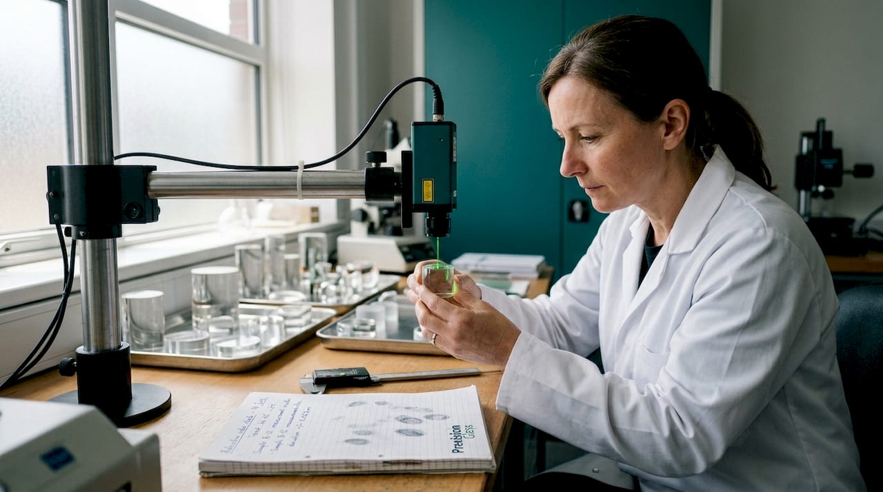
Optical glass failure in a mission-critical application is not a theoretical risk. A poorly specified lens assembly in an airborne reconnaissance system, a medical imaging component that degrades under sterilisation cycles, or a defence sight that clouds under thermal shock — these outcomes trace back directly to decisions made early in the design process. Getting optical glass design right demands more than selecting a catalogue material and sending drawings to a supplier. This guide walks you through every critical stage, from defining requirements to validating performance, with the precision your industry demands.
Table of Contents
- Understanding design requirements for optical glass
- Selecting materials, methods, and tools for precision
- Step-by-step: the optical glass design process
- Verifying and testing your optical glass design
- What most teams miss when designing optical glass
- Expert optical glass design support for your project
- Frequently asked questions
Key Takeaways
| Point | Details |
|---|---|
| Choose the right method | Select glass moulding or grinding based on application volume and required precision. |
| Understand material benefits | Glass offers superior hardness and stability compared to polymers for high-spec uses. |
| Document and test thoroughly | Careful process documentation and validation testing are critical for reliability. |
| Leverage expert support | Collaboration with specialists helps bridge design and manufacturing for dependable results. |
Understanding design requirements for optical glass
Before any material is selected or any drawing is produced, you must understand exactly what your optical glass component needs to do — and under what conditions. This sounds straightforward, but the requirement-gathering phase is where most costly errors originate. Engineers often carry over assumptions from previous projects or consumer-grade specifications into environments that demand significantly tighter tolerances.
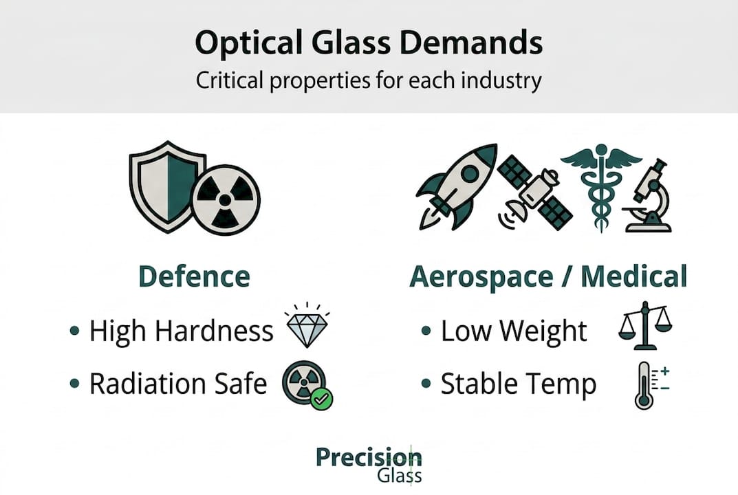
The first distinction to make is application-specific. Defence, aerospace, and medical applications each impose fundamentally different demands on optical glass.
Defence applications require glass that withstands mechanical impact, rapid temperature cycling, and often exposure to nuclear or electromagnetic radiation. Sighting systems, periscopes, and targeting optics must maintain optical fidelity after sustained vibration and potential ballistic shock.
Aerospace applications prioritise low weight combined with dimensional stability across extreme temperature ranges. Sensors and imaging systems aboard aircraft or satellites face thermal gradients that would cause conventional glass to shift focus unpredictably. Reducing the number of optical elements in a system is a consistent design goal, since every gramme matters.
Medical devices demand glass that withstands repeated sterilisation — autoclaving, gamma irradiation, and chemical exposure — without degrading transmission or dimensional accuracy. Endoscope optics, for instance, must remain stable across thousands of use and clean cycles.
Before committing to a design, your team should establish answers to these core questions:
- What is the operational wavelength range (UV, visible, near-infrared, thermal)?
- What are the environmental extremes: temperature, pressure, humidity, and radiation dose?
- What surface quality and wavefront error tolerances are acceptable?
- What are the production volumes and cost constraints?
- Are there regulatory or military standards that govern the component?
These questions determine which glass properties become non-negotiable. For a summary of critical properties across sectors, see the table below.
| Property | Defence | Aerospace | Medical |
|---|---|---|---|
| Mechanical hardness (Knoop) | >500 | >400 | >450 |
| Thermal stability (Tg) | >500°C | >480°C | >400°C |
| Radiation resistance | Critical | Moderate | High |
| Sterilisation resistance | Moderate | Low | Critical |
| Weight sensitivity | Moderate | Very high | Low |
As a baseline reference, glass outperforms polymers in hardness (Knoop >500) and thermal stability (Tg >500°C), making it the only viable choice for defence and medical applications where radiation hardness and sterility are required. Polymers may offer cost advantages for high-volume consumer products, but they cannot meet these performance thresholds reliably.
To ensure your design aligns with recognised quality benchmarks from the outset, reviewing established optical glass component standards provides a strong starting framework for your specification process.
Selecting materials, methods, and tools for precision
With requirements clearly defined, the next decision is material and fabrication method. These two choices are deeply interdependent, and selecting one without considering the other is a common mistake that leads to costly redesigns later in the programme.
Glass material selection depends primarily on your optical specifications — refractive index (nd), Abbe number (Vd), and transmission range — but also on the fabrication route you intend to use. Low-transition-temperature (low-Tg) glasses are compatible with precision moulding. High-Tg glasses offer superior thermal and radiation stability but restrict your manufacturing options.
The two dominant fabrication routes for precision optical glass are:
Traditional grinding and polishing. This is the established method for custom, high-precision components. CNC grinding machines shape blanks to near-net form, followed by iterative polishing stages to achieve surface form accuracy and roughness specifications. It suits low-to-medium volume, complex geometries, and high-hardness glass types. The trade-off is cost and cycle time, particularly for aspheric surfaces.
Precision glass moulding (PGM). This process presses heated glass against superhard moulds — typically silicon carbide (SiC) — at temperatures above the glass transition temperature, then cools under controlled conditions. PGM for aspheric lenses requires low-Tg glass (below 600°C, such as L-BSL7), isothermal pressing above Tg, and careful structural relaxation modelling to control residual stress and surface form. It reduces element count and overall system weight, making it particularly valuable in aerospace design.
Choosing between these two routes involves a clear trade-off assessment. Traditional grinding and polishing versus PGM shows that PGM excels in volume production of aspheric surfaces but is limited to lower-Tg glass types, while grinding supports custom, high-precision work at higher cost. A third and increasingly relevant option is 3D-printed gradient-index (GRIN) optics, which can reduce component weight by 20 to 50% in defence applications and enable flat optical formats not achievable with conventional forming.
“The choice of fabrication method is not purely a manufacturing decision — it should be locked in during design, because it dictates material options, tolerance achievable, and ultimately, the system’s operational reliability.”
Comparing these approaches at specification stage prevents expensive mid-programme pivots. Use this comparison to guide your decision:
| Criterion | Grinding and polishing | Precision glass moulding | 3D-printed GRIN |
|---|---|---|---|
| Volume suitability | Low to medium | Medium to high | Emerging |
| Aspheric capability | Good (costly) | Excellent | Excellent |
| Glass type flexibility | High | Low (low-Tg only) | Moderate |
| Unit cost at volume | High | Low | TBD |
| Weight reduction | Moderate | Good | Excellent |
For guidance on the full range of technical glass types available for precision applications, including material datasheets and processing notes, your specification team should review current options early in the project.
Pro Tip: Engage your fabrication supplier during the requirements phase, not after drawings are complete. Discussing material and process constraints early prevents tolerance specifications that are theoretically correct but physically unachievable within programme budgets. This is one of the most impactful process improvements you can make, alongside other structured manufacturing process improvements.
Reviewing production methods used in precision glass manufacturing also helps your team benchmark internal assumptions against what leading fabricators routinely achieve.
Step-by-step: the optical glass design process
With materials and fabrication methods selected, the design process itself follows a structured sequence. Deviating from this sequence or skipping documentation steps is a reliable path to programme delays and failed first articles.
Define the optical performance envelope. Start with system-level requirements: field of view, resolution, transmission efficiency, and environmental operating range. Use optical design software (such as Zemax or Code V) to model the initial prescription. Confirm that the glass type selected in the previous phase supports the required refractive index and dispersion.
Generate the optical prescription. Produce surface-by-surface data: radii of curvature, thickness, diameter, and any aspheric coefficients. For aspheric designs destined for PGM production, validate that the sag profile is within the mould’s capability. Document the optical prescription formally as a controlled drawing.
Define mechanical and interface specifications. Optical performance on paper means nothing if the component cannot be mounted, aligned, or retained reliably. Specify clear aperture, edge form, chamfer dimensions, and centration tolerances. For defence or aerospace assemblies, this often includes thread or flange features machined into the glass or its cell.
Specify coatings and surface treatments. Anti-reflection coatings, hard coatings, and protective overlayers form part of the optical design, not an afterthought. Specify wavelength range, reflectance limits, environmental durability class (per MIL-C-14806 or equivalent), and any restrictions on coating process temperature that might affect the glass substrate.
Produce a detailed manufacturing drawing. The drawing is the binding document between your design intent and the fabricator’s output. It must include all surface form tolerances, scratch-dig surface quality codes, transmitted wavefront error, and inspection methods. Ambiguous drawings produce ambiguous parts.
Conduct a design review before prototype release. A formal review with both optical and manufacturing engineers present catches tolerance stack-up errors, unrealistic surface quality requirements, and coating incompatibilities before any glass is cut.
Release for prototype and record first-article results. Compare measured data against drawing tolerances for every specified parameter. Document corrective actions and formally approve design changes before moving to production.
Pro Tip: Always include a tolerance sensitivity analysis in Step 2. Understanding which tolerances drive the most performance sensitivity allows you to relax non-critical parameters and reduce fabrication cost without compromising system performance. This is a key step when optimising precision glass sourcing for complex programmes.
Disciplined documentation at each step is not bureaucratic overhead. It is the mechanism by which you preserve design intent across suppliers, revisions, and programme lifecycles.
Verifying and testing your optical glass design
Completing the design and releasing drawings does not mark the end of your responsibility. Verification and testing is where design assumptions meet physical reality, and where the quality of your earlier decisions becomes measurable.
Optical glass testing falls into two categories: in-process inspection during fabrication, and post-process qualification of the finished component.
In-process inspection checks that grinding and polishing are progressing within tolerance before the component reaches its final dimensions. Interferometric measurements at intermediate stages allow corrective action while there is still material to remove. Skipping in-process checks and relying solely on final inspection is a risk that experienced fabricators consistently warn against.
Post-process qualification for defence, aerospace, and medical components typically covers:
- Surface form accuracy: Measured interferometrically, specified as peak-to-valley (P-V) or RMS wavefront error
- Surface quality: Scratch-dig rating per MIL-PRF-13830 or ISO 10110
- Transmitted wavefront error (TWE): Measures total optical path distortion through the element
- Dimensional accuracy: Centre thickness, diameter, and edge form checked against drawing limits
- Environmental performance: Thermal cycling, humidity, and where applicable, radiation exposure testing
Key standards governing optical glass qualification across your target sectors:
| Standard | Sector | Scope |
|---|---|---|
| MIL-PRF-13830 | Defence | Surface quality, cosmetic defects |
| ISO 10110 | All | Drawing notation and tolerancing |
| MIL-G-174 | Defence | Glass material quality classification |
| ISO 13485 | Medical | Quality management system for medical devices |
| ECSS-Q-ST-70 | Aerospace | European space component qualification |
As confirmed by comparative material data, glass surpasses polymers in thermal stability with Tg values exceeding 500°C, which is why validation testing for defence and medical components must be conducted on glass, not polymer substitutes, even for prototype evaluation.
“A component that passes optical bench testing but fails its environmental qualification cycle has simply deferred the problem. Test to the actual use conditions from the first prototype onwards.”
Common failure modes and their corrective actions:
- Wavefront error exceeds specification: Usually indicates surface form error in polishing. Corrective action involves additional polishing cycles with adjusted dwell time.
- Scratch-dig failure: Typically caused by handling contamination or abrasive carry-over. Corrective action involves process hygiene review and re-inspection protocols.
- Coating adhesion failure in humidity testing: Often indicates surface chemistry mismatch between glass and coating process. Requires glass surface preparation review.
Linking your optical component validation process to a documented corrective action system ensures that failure data feeds back into design and process improvement rather than simply being recorded and filed.
What most teams miss when designing optical glass
We have supported programmes across defence, aerospace, and medical sectors for many years, and one pattern recurs regardless of team experience level: the pursuit of maximum optical performance at the expense of manufacturable design.
Engineers routinely specify surface form tolerances tighter than their optical model actually requires, driven by a reasonable instinct to leave margin for error. In practice, the opposite happens. Unnecessarily tight tolerances push the component into a fabrication regime where yield drops, cost rises, and lead times extend. The result is a design that performs brilliantly on paper but creates supply chain fragility.
The second overlooked area involves technical glass challenges in sourcing. Not all glass types are available from multiple suppliers at production volumes. Specifying a glass type that only one supplier in your region can provide creates a single-point-of-failure in your supply chain. We consistently advise teams to evaluate supply availability as part of material selection, not after drawings are released.
Finally, teams underestimate the impact of coating process temperature on glass properties. Some coatings require deposition temperatures that alter the refractive index or introduce stress into low-Tg substrates. Aligning the coating specification with the glass type before finalising either is a straightforward step that prevents significant rework.
Optimise for the system as a whole: performance, manufacturability, and supply resilience together.
Expert optical glass design support for your project
Designing precision optical glass for defence, aerospace, or medical applications requires more than technical knowledge — it requires a fabrication partner who understands the full journey from specification to qualification.
At Glass Precision, we work alongside your engineering and product development teams from the earliest design stages, providing material selection guidance, tolerance review, and meticulous fabrication of precision optical components tailored to your exact operational requirements. Whether you need a single prototype for qualification testing or a production-volume supply of complex aspheric lenses, our state-of-the-art processes and unwavering commitment to quality assurance deliver results you can rely on. Explore our aerospace-strength glass solutions to see how we support demanding programmes from concept through to delivery.
Frequently asked questions
What factors are most critical when designing optical glass for defence use?
Mechanical hardness, radiation resistance, and thermal stability are essential for defence applications, with glass consistently outperforming polymers across all three criteria — particularly for components requiring Knoop hardness above 500 and high Tg values.
Why is precision glass moulding suitable for aerospace optics?
Precision glass moulding enables production of lightweight, high-quality aspheric lenses that reduce element count and system weight. PGM using low-Tg glass with superhard SiC moulds delivers the dimensional accuracy and structural consistency aerospace programmes require.
Are polymers ever an alternative to glass in high-spec optics?
Polymers offer cost advantages for consumer applications but cannot provide the hardness and radiation resistance that defence and medical precision optics demand. For mission-critical components, glass is the only appropriate choice.
How does 3D-printed GRIN glass impact optical glass design?
3D-printed GRIN (gradient-index) optics enable flat optical formats and can reduce component weight by 20 to 50% compared with conventional lens assemblies, making them a compelling emerging option for weight-sensitive defence applications.
Recommended
- How to optimise glass sourcing for precision: 5 key steps – Precision Glass
- Top glass solutions for aerospace: strength, clarity, precision – Precision Glass
- Display glass explained: precision, performance and industry solutions – Precision Glass
- Precision Glass – Medical – Defense – Engineering – Security – Optical – Automotive – Electronic