The glass selection process for electronics is a structured engineering discipline that balances electrical, mechanical, optical, and manufacturing criteria to determine which glass material will deliver reliable device performance across its intended operating life. Glass serves as substrate, cover, and optical component across virtually every electronics category, from 5G mmWave modules and TFT-LCD panels to automotive radar circuits and medical imaging sensors. The four primary glass families relevant to electronics are fused silica, borosilicate, aluminosilicate, and soda-lime, each with distinct property profiles that suit different functional roles. Selecting the wrong type affects signal integrity, manufacturing yield, and long-term durability. Understanding the performance and reliability implications of each material is the starting point for any sound engineering decision.
What electrical and thermal criteria guide glass selection in electronic components?
Electrical performance is the primary filter in the glass selection process for electronics operating above a few gigahertz. The two properties that matter most are the dielectric constant (Dk) and the loss tangent (Df). Dk determines signal propagation speed, while Df quantifies how much signal energy is absorbed by the substrate as heat. At high frequencies, even small differences in Df produce measurable signal degradation over short path lengths.
Fused silica suits frequencies above 60 GHz because its Df falls below approximately 0.0005, making it the preferred substrate for millimetre-wave radar, satellite communication modules, and advanced 5G antenna arrays. That figure is roughly ten times lower than borosilicate, which means fused silica substrates lose a fraction of the signal energy per unit length compared to alternatives. For designs operating between 10 GHz and 60 GHz, borosilicate’s Df of 0.004 to 0.006 and a coefficient of thermal expansion (CTE) of approximately 3.3 ppm per degree Celsius make it a practical default for 5G mmWave and automotive radar circuits. This CTE value sits close enough to silicon and gallium arsenide to reduce interfacial stress during thermal cycling.
Thermal expansion matching is not optional. When the CTE of the glass substrate diverges significantly from the semiconductor die or solder interconnects bonded to it, thermal cycling generates stress that causes delamination, cracking, or via failure. Strain point is equally relevant: the temperature at which glass begins to deform under load must exceed the highest processing temperature in the assembly sequence. For TFT-LCD substrates, strain points above 650°C are required to survive the thermal budgets of thin-film transistor deposition without dimensional distortion.
| Glass type | Dk (approx.) | Df (approx.) | CTE (ppm/°C) | Typical application |
|---|---|---|---|---|
| Fused silica | 3.8 | <0.0005 | 0.55 | >60 GHz RF, mmWave |
| Borosilicate | 4.6 | 0.004–0.006 | 3.3 | 5G, automotive radar |
| Aluminosilicate | 6.0–7.0 | 0.006–0.010 | 7–9 | Cover glass, displays |
| Soda-lime | 7.2 | 0.010–0.015 | 8.5–9.0 | Low-frequency, low-cost |
Pro Tip: When specifying glass for a new RF design, request Df data at your actual operating frequency from the supplier. Published values are often measured at 1 MHz and can understate loss at 28 GHz or above by a factor of two or more.
How do mechanical and chemical factors influence glass selection for durable electronics?
Mechanical durability determines whether a glass component survives the assembly process, the product’s service life, and any regulatory drop or impact tests. The relevant properties include surface hardness, fracture toughness, and resistance to sub-critical crack growth under sustained load. For consumer devices, cover glass must resist scratching from keys and abrasive surfaces without developing micro-cracks that propagate under bending stress.
Aluminosilicate glass chemical strengthening increases surface hardness and fracture resistance by four to six times compared to standard soda-lime glass. The ion exchange process replaces sodium ions near the surface with larger potassium ions, creating a compressive stress layer that resists crack initiation. This is why chemically strengthened aluminosilicate is the dominant material for smartphone cover glass and ruggedised industrial display panels.
Chemical stability matters equally in substrate applications. Alkali ions, particularly sodium and potassium, migrate under electric fields and contaminate thin-film transistor channels, degrading switching behaviour and threshold voltage stability. Alkali-free glass formulations are therefore mandatory for TFT-LCD and OLED backplane substrates. Neglecting this requirement causes subtle yield losses that only appear after thermal cycling, making root cause analysis difficult and expensive.
Key mechanical and chemical criteria to evaluate during material selection:
- Surface hardness (Vickers or Mohs): Determines scratch resistance in consumer and industrial environments.
- Fracture toughness (K1c): Governs resistance to crack propagation from surface defects introduced during handling or laser processing.
- Alkali content: Must be near zero for TFT, OLED, and similar thin-film processes.
- Chemical resistance to process fluids: Wet etching, cleaning agents, and photoresist strippers must not attack the glass surface or alter its flatness.
- Warpage under thermal load: Thin substrates below 300 micrometres are particularly susceptible; flatness specifications must be confirmed at process temperature, not only at room temperature.
Pro Tip: Request a material safety data sheet and a chemical compatibility table from your glass supplier before committing to a substrate. Process chemistry incompatibilities discovered during pilot runs are among the most disruptive and costly late-stage surprises in electronics manufacturing.
What manufacturing processes affect glass choice for electronics?
Fabrication method compatibility is a constraint that narrows the list of viable glass types before electrical or mechanical properties are even considered. The three most consequential manufacturing steps are via formation, singulation, and laser processing of thin or chemically strengthened sheets.
Femtosecond laser processing reduces heat-affected zones to negligible levels, which is critical when cutting glass thinner than 100 micrometres. Picosecond lasers offer a practical middle ground for thicker substrates where throughput matters more than absolute precision. Chemically strengthened aluminosilicate requires femtosecond processing because the compressive stress layer shatters unpredictably under the thermal shock of longer-pulse lasers, producing edge defects that initiate fracture during assembly.
Stack-up symmetry directly controls warpage in glass interposer designs. Copper imbalance and dielectric mismatch across the stack cause warpage and yield loss during reflow. Symmetrical redistribution layer arrangements and matched CTE dielectrics on both sides of the glass core are not optional refinements. They are design requirements that must be confirmed in simulation before the first prototype panel is ordered.
| Glass type | Laser via formation | Mechanical singulation | Chemical strengthening compatible | Warpage risk (thin substrates) |
|---|---|---|---|---|
| Fused silica | Excellent | Difficult | No | Low |
| Borosilicate | Good | Moderate | Limited | Low to moderate |
| Aluminosilicate | Good (femtosecond) | Moderate | Yes | Moderate |
| Soda-lime | Moderate | Easy | Limited | Moderate to high |
Changing glass type late in development creates pilot run surprises because via geometry, conductor adhesion, and handling fixtures are all optimised for the original material. Early integration of glass type with stack-up design, conductor strategy, and handling processes avoids yield losses that are expensive to diagnose and correct at the pilot stage.
Pro Tip: Involve your glass supplier in the design review at the schematic stage, not after the layout is complete. Suppliers with fabrication experience can flag process incompatibilities in minutes that would otherwise take weeks to discover during prototyping.
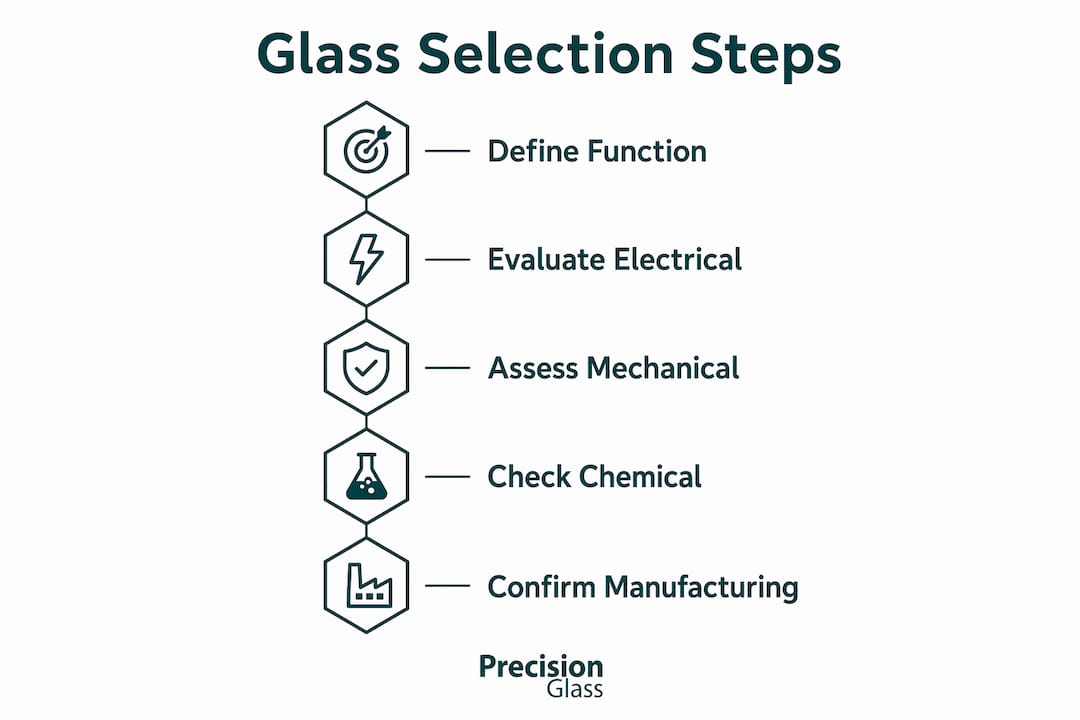
How to apply a step-by-step framework for selecting glass materials
The first priority in glass selection is defining the functional role the glass plays in the product. Treating glass as a direct material substitute for an existing substrate leads to errors in transparency, flatness, and optical role assumptions. A structured selection framework prevents this.
- Define functional requirements. State explicitly whether the glass serves as a substrate, cover, optical window, or interposer. Each role carries different primary property requirements.
- Specify operating conditions. Document operating frequency range, temperature extremes, humidity exposure, and any chemical environments the glass will encounter in service.
- Set mechanical load criteria. Identify drop test standards, surface hardness targets, and any bending or compressive loads from assembly or end-use.
- Screen glass types against a property matrix. Use a comparison matrix with Dk, Df, CTE, strain point, alkali content, and hardness as columns. Eliminate types that fail any mandatory criterion.
- Assess manufacturing compatibility. Confirm that your preferred glass type is compatible with your via formation method, singulation process, and any chemical strengthening or coating steps.
- Prototype and qualify. Fabricate test coupons using the selected glass and subject them to thermal cycling, mechanical testing, and electrical characterisation under realistic conditions.
- Qualify the supplier. Confirm lot-to-lot consistency, dimensional tolerances, and delivery lead times before committing to a production volume.
Common pitfalls include ignoring CTE mismatch between glass and die attach materials, specifying chemically strengthened glass without confirming laser processing compatibility, and deferring glass selection until after the PCB layout is finalised. Glass core substrates are anticipated to gain production traction from 2028, driven by AI and high-performance computing demand. Engineers qualifying materials today should factor this trajectory into their roadmap planning, particularly if their products will require re-qualification against next-generation packaging formats.
For a practical reference during the screening step, the glass material selection list from Glassprecision provides structured comparisons across precision engineering applications, including electronics substrates and cover glass.
Key takeaways
The glass selection process for electronics requires systematic evaluation of electrical, mechanical, chemical, and manufacturing criteria in sequence, with functional role definition as the mandatory first step.
| Point | Details |
|---|---|
| Define function before material | Identify whether glass is a substrate, cover, or optical component before evaluating any property data. |
| Match Df to operating frequency | Use fused silica above 60 GHz and borosilicate for 10 to 60 GHz designs to control signal loss. |
| Specify alkali-free for TFT processes | Alkali contamination degrades transistor performance; alkali-free formulations are mandatory for display substrates. |
| Integrate glass selection early | Late material changes disrupt via geometry, conductor adhesion, and handling processes, increasing yield loss risk. |
| Qualify supplier before production | Confirm lot-to-lot consistency and dimensional tolerances during prototyping, not after volume commitment. |
Why I think engineers underestimate glass selection until it’s too late
After working closely with engineering teams across display, RF, and packaging programmes, the pattern I observe most consistently is this: glass selection is treated as a procurement decision rather than a design decision. Teams finalise their stack-up, complete their layout, and then ask a supplier to quote a glass substrate. That sequence is backwards, and it costs time and money every time.
The trade-offs between glass properties and manufacturing capabilities are genuinely complex. Fused silica offers outstanding electrical performance but is brittle, difficult to singulate mechanically, and incompatible with standard chemical strengthening processes. Aluminosilicate offers excellent mechanical durability but its higher Dk and Df make it unsuitable for frequencies above roughly 20 GHz. No single glass type wins across all criteria, which is precisely why the selection decision must be made collaboratively, with designers, process engineers, and suppliers at the same table.
Thorough prototyping under realistic thermal and mechanical conditions is non-negotiable. I have seen programmes skip coupon-level thermal cycling tests to save three weeks, only to discover CTE-driven delamination failures during system-level qualification, which cost months. The advanced glass specifications guide from Glassprecision is a useful reference for structuring those qualification conversations with suppliers early in the programme.
Supply chain considerations also deserve more attention than they typically receive. Glass substrates for high-frequency applications are not commodity items. Lead times for precision-ground, tight-tolerance fused silica panels can exceed twelve weeks. Building that into your programme schedule from the outset, rather than discovering it at the prototype order stage, is the difference between a smooth development cycle and a delayed product launch.
— Alexandra
Precision glass solutions for your electronics development
Glassprecision designs, fabricates, and supplies precision glass components for electronics programmes where material performance and dimensional accuracy are non-negotiable. From technical glass substrates for high-frequency circuits to chemically strengthened cover glasses and optical windows for sensor assemblies, the product range covers the full spectrum of glass materials in electronics.

The manufacturing process at Glassprecision integrates meticulous quality assurance at every stage, from raw material inspection through grinding, polishing, and toughening to final dimensional verification. Engineers and project managers working on demanding electronics applications can access technical resources, material data, and direct consultation through the Glassprecision electronics solutions page. Whether you are qualifying a substrate for a 5G module or specifying cover glass for a ruggedised industrial display, Glassprecision brings the fabrication expertise and material knowledge your programme requires.
FAQ
What is the glass selection process for electronics?
The glass selection process for electronics is a structured engineering method for identifying the most suitable glass material based on functional role, electrical properties, mechanical requirements, and manufacturing compatibility. It begins with defining whether the glass serves as a substrate, cover, or optical component, then screens candidate materials against property criteria such as dielectric loss, CTE, and chemical stability.
Which glass type is best for high-frequency RF circuits?
Fused silica is the preferred choice for operating frequencies above 60 GHz due to its dielectric loss factor below approximately 0.0005. Borosilicate is the standard selection for designs operating between 10 GHz and 60 GHz, where its CTE of 3.3 ppm per degree Celsius also provides good compatibility with semiconductor packaging materials.
Why does alkali content matter when choosing glass for displays?
Alkali ions migrate under electric fields and contaminate thin-film transistor channels in TFT-LCD and OLED panels, causing threshold voltage instability and yield loss. Substrate glass for display applications must use alkali-free formulations with strain points above 650°C to maintain dimensional stability through thin-film deposition processes.
How does chemical strengthening affect glass selection for consumer electronics?
Chemical strengthening through ion exchange increases the surface hardness and fracture resistance of aluminosilicate glass by four to six times compared to standard soda-lime glass. This process creates a compressive stress layer that resists crack initiation, making chemically strengthened aluminosilicate the dominant cover glass material for smartphones and ruggedised displays.
When should glass type be decided in an electronics development project?
Glass type should be decided at the schematic or early layout stage, before stack-up design and conductor routing are finalised. Changing glass late in development disrupts via geometry, conductor adhesion, and handling processes, and typically causes yield losses that are costly to diagnose during pilot production runs.