In defence, aerospace, and medical device manufacturing, a tolerance error of just a few micrometres can ground a programme, delay regulatory approval, or compromise a critical system. Glass component design is not forgiving. Procurement managers and design engineers frequently encounter costly rework cycles because material specifications were left ambiguous, thermal mismatch went unmodelled, or suppliers lacked the vertical integration to guarantee process consistency. This guide sets out a proven, methodical process for achieving high-precision glass components from initial requirements through to final quality verification and emerging technologies.
Table of Contents
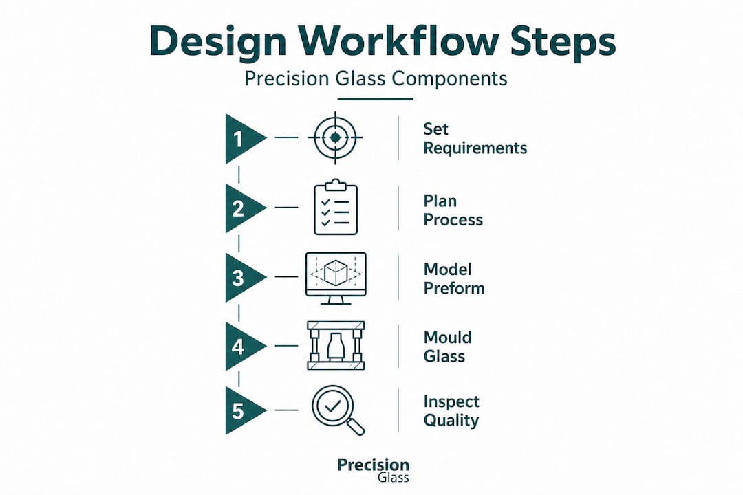
- Setting requirements: Material, performance, and tolerance criteria
- Process planning: Preform design, FEA, and supplier selection
- Precision glass moulding: Step-by-step execution
- Quality assurance and troubleshooting: Surface, edge, and hermetic tests
- Emerging technologies: Wafer-level, 3D-printed GRIN, rapid moulding
- A fresh perspective: Avoiding the hidden traps in glass component design
- Ready for ultra-precise glass components?
- Frequently asked questions
Key Takeaways
| Point | Details |
|---|---|
| Define clear requirements | Set precise material, tolerance, and performance criteria before design begins. |
| Plan with FEA and supplier benchmarking | Early modelling and choosing qualified partners avoid costly mistakes. |
| Control process parameters tightly | Strict temperature, mold material, and cooling control deliver accuracy and reliability. |
| Verify post-production quality | Edge processing, photoelastic tests, and hermeticity checks safeguard performance. |
| Embrace new technologies | Wafer-level, 3D printing, and rapid molding change what’s possible in precision glass design. |
Setting requirements: Material, performance, and tolerance criteria
Every successful precision glass component begins with clearly defined requirements. Before any design geometry is drawn or supplier contacted, you need a complete specification document covering material type, performance targets, tolerance thresholds, and interface conditions. Ambiguity at this stage propagates through every subsequent step and multiplies cost.
Selecting the right glass type is the first decision. Optical glass catalogues from manufacturers such as SCHOTT and Ohara offer hundreds of glass types, each with distinct refractive indices, Abbe numbers, and thermal properties. For infrared optics used in defence thermal imaging, chalcogenide or germanate glasses may be appropriate. For precision surgical instruments in medical devices, SCHOTT N-BK7 or P-SK57 provide stable performance across sterilisation cycles. Matching the glass type to the application environment, rather than defaulting to a familiar material, is fundamental to long-term reliability.
Critical tolerance values must be specified at the outset. According to the precision glass molding technical brief, precision glass moulding achieves diameter tolerances of +0/−0.010 mm, centre thickness of ±0.010 mm, and surface roughness of 5 Å rms. These benchmarks inform what is achievable and set realistic expectations during procurement discussions. Refer to our engineering specifications guide for a structured template aligned to defence and medical applications.
For thermal and mechanical requirements, specify the operating temperature range, thermal shock resistance, and any vibration or impact loading. Medical sterilisation cycles impose repeated thermal cycling, whilst aerospace components must survive cryogenic temperatures at altitude. Document these conditions explicitly.
| Parameter | Achievable benchmark | Typical application |
|---|---|---|
| Diameter tolerance | +0/−0.010 mm | Optical lenses, viewports |
| Centre thickness | ±0.010 mm | Beam splitters, filter windows |
| Surface roughness | 5 Å rms | High-power laser optics |
| Hermeticity | <1×10⁻⁸ cc He/sec | Medical implants, sealed sensors |
Hermetic sealing and coefficient of thermal expansion (CTE) matching are critical for glass-to-metal assemblies common in aerospace feedthroughs and medical implantable devices. The glass CTE must be matched to the metal housing, whether Kovar, stainless steel, or titanium. CTE mismatch creates residual stress at the interface, which leads to seal failure under thermal cycling. Document the metal alloy and its CTE alongside the glass specification so that supplier engineers can validate compatibility immediately.
Key requirements to document at this stage:
- Glass type and catalogue designation (manufacturer, melt number where possible)
- Refractive index and Abbe number at specified wavelengths
- Diameter, thickness, and wedge tolerances
- Surface form and roughness targets
- Operating temperature range and thermal shock requirement
- Interface metal type and CTE value
- Sterilisation or cleaning method compatibility
Process planning: Preform design, FEA, and supplier selection
With requirements defined, the next stage is process planning. This is where many projects either gain a decisive advantage or accumulate hidden risk. Preform geometry, finite element analysis, and supplier qualification all happen here.
Preform shape modelling determines how the glass blank will flow during moulding. A poorly designed preform introduces asymmetric material distribution, which results in thickness variation and surface form errors that are extremely difficult to correct post-mould. Preform modelling uses glass viscosity data at temperature to simulate material flow and predict final shape. Investing time in this step reduces first-article failure rates significantly.
FEA for stress and thermal analysis is vital for CTE matching and minimising post-moulding stress. Running thermal FEA before committing to tooling allows you to identify stress concentration zones at glass-to-metal interfaces and adjust either the geometry or the glass type. This is especially relevant for medical device assemblies where post-sterilisation cracking would be a critical failure mode.
Supplier selection deserves as much rigour as material selection. The distinction between a supplier who subcontracts polishing, coating, and inspection separately versus one who handles all steps in-house is profound. Vertically integrated suppliers reduce lead time, but more importantly, they maintain process traceability across every step. Accountability does not get diluted between multiple sub-vendors. Benchmarking supplier capabilities should follow a structured process.
- Request documented process capability data for your specific tolerance targets.
- Confirm in-house access to relevant metrology equipment (interferometers, profilometers, coordinate measuring machines).
- Verify quality certifications relevant to your sector (ISO 13485 for medical, AS9100 for aerospace).
- Assess whether the supplier uses FEA during preform design or relies on trial-and-error iteration.
- Review lead time guarantees and their basis, whether capacity-driven or tooling-limited.
Review our manufacturer partnership advice for a structured framework on qualifying suppliers, and consult our glass engineering basics resource to align your internal team’s vocabulary with supplier discussions.
Comparison of supplier integration models:
| Supplier model | Lead time risk | Traceability | Cost control |
|---|---|---|---|
| Fully vertically integrated | Low | High | Predictable |
| Partially integrated | Medium | Moderate | Variable |
| Subcontracted supply chain | High | Low | Unpredictable |
Pro Tip: Request FEA outputs from shortlisted suppliers before placing a tooling order. A supplier who cannot provide stress contour maps for your glass-to-metal interface has likely not modelled the assembly at all. This is a clear differentiator between capable and under-resourced vendors.
Precision glass moulding: Step-by-step execution
With a validated process plan, execution of precision glass moulding follows a well-defined sequence. Each step demands close control of parameters that directly affect final optical and mechanical performance.
Precision glass moulding (PGM) involves heating a glass preform above its transition temperature (Tg), pressing it in ultra-precision moulds such as tungsten carbide, and applying controlled cooling to minimise index drop and residual stress. The moulds replicate surface form to sub-micrometre accuracy, which is why mould material selection and maintenance are as critical as the glass itself.
The full execution sequence:
- Preform preparation: Clean and inspect preforms for surface defects, chips, or contamination. Any particulate trapped at the mould interface will replicate into the final surface.
- Furnace loading and atmosphere control: Load preforms into a nitrogen or forming-gas atmosphere furnace to prevent mould oxidation. Oxygen at temperature degrades tungsten carbide mould surfaces within very few cycles.
- Heating to above Tg: Bring the glass to the moulding temperature, typically 50°C to 150°C above Tg depending on the glass type. SCHOTT and Ohara datasheets specify viscosity curves that guide this selection.
- Press cycle: Apply the pressing load profile with precise force and dwell time control. Under-pressing results in surface form errors; over-pressing risks mould contact damage.
- Controlled annealing: Cool the pressed component through the annealing range slowly to relieve residual stress. Rapid cooling introduces birefringence, which degrades polarisation-sensitive optical performance.
- Demolding and initial inspection: Remove the component and perform a first visual and dimensional check before the component proceeds to further processing.
“Refractive index drop during moulding, typically 1 to 2%, must be anticipated using preform predictor tools. Designing the preform with this compensation built in prevents costly rework at the final inspection stage.”
For a detailed walkthrough of our manufacturing workflow, visit our manufacturing workflow details page.
Glass selection during execution matters beyond the preform stage. SCHOTT and Ohara glasses have different moulding behaviour curves. Some glass types exhibit greater structural relaxation sensitivity, meaning that even modest deviations in cooling rate shift the final refractive index outside specification. Knowing which glass types are forgiving and which require tighter temperature control allows process engineers to adjust their monitoring intervals accordingly.
Quality assurance and troubleshooting: Surface, edge, and hermetic tests
Moulding execution must be followed by a structured quality assurance programme. For defence and medical applications, quality assurance is not an optional final check. It is a contractual and regulatory obligation.
Surface quality standards require both roughness and irregularity measurements. Surface roughness of 5 Å rms, as confirmed by empirical benchmarks in precision glass moulding, is achievable and should be the target for high-performance optical surfaces. Interferometric measurement of surface irregularity (departure from the ideal form, expressed in waves or nanometres) must be recorded and compared against specification for every critical surface.
Edge quality is frequently underspecified and underinspected. Chips, micro-cracks, and edge chamfer inconsistencies act as stress concentrators, particularly in thermally cycled assemblies. Photoelastic quality control (measuring internal stress distribution using polarised light) improves edge strength and provides a non-destructive method to assess the residual stress state across the entire component.
Hermeticity testing is mandatory for medical implants, sealed aerospace windows, and sensor feedthroughs. Helium leak testing using mass spectrometry is the standard approach, with a target leak rate below 1×10⁻⁸ cc He/sec for high-reliability applications. Gross leak testing using fluorocarbon immersion can precede fine leak testing to filter out gross failures before consuming time on mass spectrometry.
Key quality assurance checks to include in your inspection plan:
- Interferometric surface form measurement (every optical surface)
- Profilometer surface roughness measurement (sample or 100% depending on criticality)
- Dimensional verification (diameter, thickness, wedge) using a calibrated coordinate measuring machine
- Photoelastic inspection for residual stress and edge strength
- Helium fine leak test for hermetic assemblies
- Refractive index verification using a calibrated refractometer
Common troubleshooting scenarios and their root causes:
- Index drop outside specification: Cooling rate too fast or glass type susceptible to structural relaxation. Slow the annealing rate or switch to a less relaxation-sensitive glass.
- Surface form error: Preform mass or geometry incorrect, or mould wear. Re-evaluate preform predictor output and inspect mould surface form.
- CTE mismatch failure at interface: Thermal analysis was not performed or wrong glass type was selected. Return to FEA modelling with corrected material inputs.
Pro Tip: Incorporate photoelastic inspection as a standard step, not an escalation response. Stress distributions that appear acceptable visually can still produce fatigue failure after thousands of thermal cycles. Catching this early saves significant downstream rework costs.
Explore our precision fabrication processes and quality control criteria for the full scope of inspection methods we apply across defence and medical programmes.
Emerging technologies: Wafer-level, 3D-printed GRIN, rapid moulding
The precision glass industry is not static. Several technologies are reshaping what is achievable in both volume production and custom optical design.
Wafer-level moulding, rapid heating cycles, and 3D-printed GRIN optics are emerging as significant capabilities, particularly for reducing curvature requirements in compact defence systems. These technologies alter how design engineers should approach component architecture from the earliest stages.
Emerging approaches worth considering:
- Wafer-level moulding: Multiple optical elements are pressed simultaneously on a single glass wafer, then diced. This approach dramatically reduces per-unit cost for high-volume applications such as night-vision image intensifiers or medical endoscope lenses.
- Rapid heating moulding cycles: New furnace control systems reduce cycle time by 30 to 50% without compromising temperature uniformity. Throughput gains make precision moulding economically viable for medium-volume aerospace programmes that previously relied on grinding and polishing.
- 3D-printed gradient index (GRIN) optics: Additive manufacturing of glass with spatially varying refractive index eliminates the need for complex multi-element assemblies. A single GRIN element can replace a three or four element lens group, reducing size, weight, and assembly risk. This is particularly valuable for wearable defence systems and compact medical imaging devices.
- Advanced mould materials: Beyond tungsten carbide, silicon carbide and diamond-like carbon coatings are extending mould life and enabling finer surface replication for aspheric forms.
Staying ahead of these developments gives procurement managers a sourcing advantage and gives design engineers more architectural options at the concept stage. Review our emerging technologies overview and designing optical glass steps to understand how these capabilities apply to your sector.
A fresh perspective: Avoiding the hidden traps in glass component design
The most avoidable failures we encounter in glass component design share a common characteristic. They stem not from lack of technical knowledge, but from process shortcuts that were accepted early and never questioned again.
Skipping FEA during the preform design stage is the single most common shortcut. Engineers and procurement managers often justify it by saying the geometry is straightforward or that the supplier has made something similar before. Neither justification is sufficient. CTE mismatch failures in glass-to-metal assemblies almost always trace back to a thermal model that was never run. The correction cost, measured in tooling scrapped, assemblies disassembled, and programme delays, is vastly disproportionate to the cost of the analysis itself.
Photoelastic quality control is another capability that is frequently treated as optional. Many programmes specify interferometry and dimensional checks, then skip the stress measurement. This is precisely backwards for applications that will experience thermal cycling. A component can pass every optical specification and still carry sufficient residual stress to fail after fifty sterilisation cycles. Stress measurement is not a luxury. It is a requirement for long-term reliability in demanding environments.
The third trap is supplier accountability diluted across a fragmented supply chain. When polishing happens at one subcontractor, coating at another, and inspection at a third, traceability becomes a documentation exercise rather than a genuine quality process. We have seen programmes where a coating vendor altered their process without notifying the prime supplier, and the first indication was yield failure at final inspection. Vertically integrated supply is not about speed alone. It is about maintaining a single point of accountability for every variable that affects your component’s performance.
Explore the full range of sector-specific solutions to see how these principles apply directly to your application area.
Ready for ultra-precise glass components?
Achieving the tolerances and reliability standards that defence, aerospace, and medical device programmes demand requires more than capable equipment. It requires a partner with meticulous process control, validated quality systems, and the technical depth to support your design from specification through delivery.

At Precision Glasses, we combine certified quality standards with cutting-edge glass technologies to deliver components that perform in the most demanding environments. Whether you are designing precision optics for a new medical imaging system, a defence sensor window, or a high-reliability aerospace assembly, our engineering team is ready to support your programme from the earliest specification stage. Explore our full range of optical glass solutions and contact us to discuss your requirements with a specialist.
Frequently asked questions
What are the tightest achievable tolerances in precision glass components?
Diameter tolerances can be as tight as +0/−0.010 mm and centre thickness as ±0.010 mm, with surface roughness reaching 5 Å rms in precision glass moulding processes.
How is thermal expansion matched between glass and metals?
Custom glass pressing matches the CTE of glass to metals such as Kovar or stainless steel, minimising residual stress at the interface and ensuring seal integrity through thermal cycling.
What new technologies are emerging for high-precision glass design?
Wafer-level moulding, rapid heating cycles, and 3D-printed GRIN optics are reshaping glass component manufacturing by improving throughput, reducing assembly complexity, and enabling new optical architectures.
How do engineers minimise index drop during glass moulding?
Index drop of 1 to 2% during moulding can be managed by using preform predictor tools to compensate in the preform design and by applying precisely controlled, slow cooling rates through the annealing temperature range.
Why is photoelastic quality control important?
Photoelastic QC reveals residual stress distributions that standard optical inspection misses, improving edge strength and reducing the risk of fatigue failure in components subjected to repeated thermal cycling or mechanical loading.