
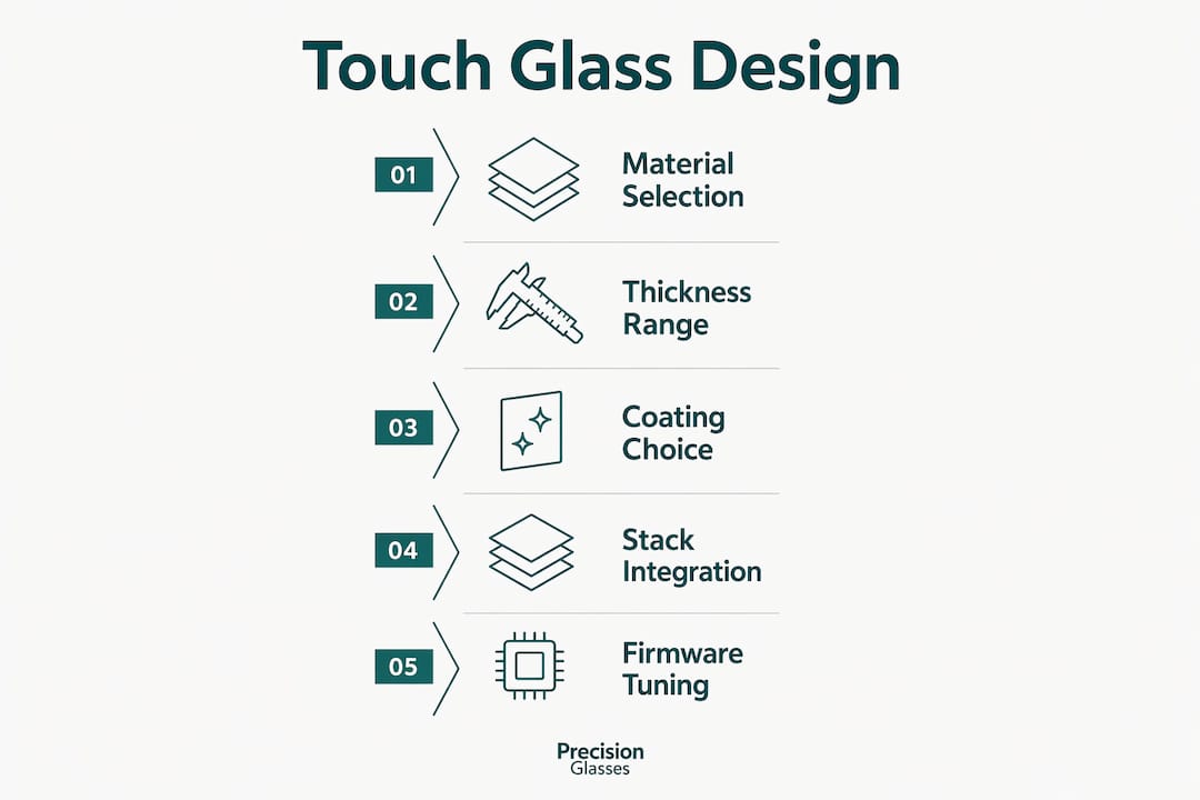
Touch screen glass design is the process of selecting and integrating cover glass materials, coatings, and stack configurations to deliver reliable touch performance and mechanical durability across an application’s full service life. Getting it right demands more than choosing a glass type. Engineers must balance IEC 62262 IK impact ratings, projected capacitive (PCAP) thickness constraints of 0.55–1.8 mm, optical transmittance targets above 90%, and full stack integration from sensor to controller firmware. The core trade-off in every cover glass project is this: thicker glass protects better but attenuates the touch signal. Understanding that trade-off early determines whether a design succeeds in production or fails in the field.
What materials and thickness ranges are best for touch screen glass?
The material you specify for cover glass directly controls touch sensitivity, mechanical strength, and total cost. Three glass types dominate the field, each with distinct properties suited to different applications.
Common cover glass materials:
- Soda-lime glass is the lowest-cost option. It suits light-use, controlled environments, and costs 20–30% less than chemically strengthened alternatives. That cost advantage disappears quickly in high-use deployments where breakage and warranty claims accumulate.
- Chemically strengthened aluminosilicate glass (such as Corning Gorilla Glass or AGC Dragontrail) offers high surface compressive stress, excellent scratch resistance, and good optical clarity. It is the standard choice for industrial HMIs and consumer electronics.
- Borosilicate glass provides superior thermal stability and chemical resistance. It suits medical and laboratory environments where sterilisation cycles or chemical exposure are routine.
Thickness is the single most consequential specification in PCAP design. PCAP cover glass must stay within 0.55–1.8 mm to maintain compatibility with mutual capacitance sensing. Resistive touch designs tolerate a wider range because activation depends on physical pressure rather than capacitive coupling. For extreme impact protection, glass up to 10–12 mm is possible, but only with self-capacitance sensing modes. Self-capacitance sacrifices multi-touch capability, so that trade-off must be accepted at the specification stage.
| Glass type | Typical thickness | Best application | Key limitation |
|---|---|---|---|
| Soda-lime | 1.0–4.0 mm | Low-use, indoor kiosks | Low impact resistance |
| Aluminosilicate | 0.55–2.0 mm | Industrial HMI, consumer devices | Higher unit cost |
| Borosilicate | 1.0–3.0 mm | Medical, laboratory displays | Heavier than aluminosilicate |

Pro Tip: Specify your glass thickness before selecting a touch controller. Controllers have fixed sensitivity ranges, and retrofitting a thicker glass panel after controller selection often requires a complete firmware redesign.
Thermal and chemical strengthening processes alter compressive stress levels in the glass surface, significantly improving impact resistance. Chemically strengthened glass achieves compressive stress layers of 50–100 µm depth, which is far deeper than thermally tempered equivalents at equivalent thickness. This matters in thin-glass PCAP designs where thermal tempering is not viable below approximately 2.5 mm.
How to balance impact resistance, optical clarity, and touch responsiveness
Impact resistance requirements must drive glass thickness selection. IEC 62262 IK ratings define the impact energy levels a product must withstand, and each IK level corresponds to a minimum practical glass thickness. Specifying thickness without reference to the required IK rating produces a design that either over-engineers cost or fails field testing.
Optical performance targets are equally non-negotiable. Cover glass transmittance above 90% is the baseline for display-quality applications. Three coating types address different optical and usability problems:
- Anti-glare (AG) coatings scatter incident light to reduce specular reflections. Haze values typically run 5–25%, with higher haze improving outdoor readability at the cost of image sharpness.
- Anti-reflective (AR) coatings use thin-film interference to achieve reflection below 0.5%. They are the preferred choice for medical displays where colour accuracy and contrast are critical.
- Anti-fingerprint (AF) / oleophobic coatings raise the water contact angle above 110 degrees, improving cleanability. These coatings degrade after approximately 1,500 abrasion cycles, so lifecycle expectations must inform the specification.
The interaction between coatings and touch sensitivity is frequently underestimated. AG coatings with high haze values scatter the electric field slightly, which can reduce signal-to-noise ratio at the sensor. AR coatings have negligible electrical effect but add cost and fragility. Oleophobic layers have no measurable impact on capacitive sensing but must be applied after any laser cutting or edge finishing to avoid delamination.
Doubling glass thickness reduces signal strength to approximately 25% of its original level. That is not a linear degradation. It is a square-law relationship between finger-to-sensor distance and signal amplitude. Every millimetre added to the cover glass demands a corresponding adjustment in controller gain and noise filtering parameters.
What are the best practices for integrating touch screen glass with sensors and displays?
The touch screen stack cannot be designed component by component. Defining the full stack holistically, including cover glass, sensor film or glass, adhesive, display module, and controller electronics, is the only approach that avoids tolerance conflicts and signal failures in production.
The assembly method between cover glass and display is a critical decision:
- Optical bonding fills the air gap between cover glass and display with optically clear resin (OCR) or optically clear adhesive (OCA). This eliminates internal reflections at the glass-air interface, improving contrast and reducing dust and moisture ingress. Optical bonding is the correct choice for outdoor, automotive, and medical applications.
- Air gap assembly retains a physical separation between cover glass and display. It costs less and simplifies replacement, but the air-glass interfaces introduce reflections that reduce sunlight readability and create condensation risk in humid environments.
- Edge design and finishing directly affects mechanical reliability. Chamfering and polishing glass edges reduces stress concentrations that cause fracture. Poor edge finishing is the primary failure point in field-deployed touch glass covers, not the glass face itself.
- Decorative printing on the glass border (typically ceramic ink or UV-cured ink) must be specified with touch sensor field boundaries in mind. Decorative printing overlapping sensor fields without proper grounding and shielding causes ghost touches. This is one of the most common and most avoidable design errors.
Pro Tip: Request a full stack drawing from your glass supplier before finalising the sensor layout. Adhesive thickness tolerances of ±0.05 mm compound across layers and can shift the effective glass-to-sensor distance enough to require controller re-tuning.
Controller firmware tuning is the final integration step, not an afterthought. Gain, noise filtering, and signal threshold parameters must be adjusted to compensate for cover glass thickness, coating type, and operating environment. Glove operation and wet-finger detection both require specific firmware modes that the controller must support from the outset of component selection.
What common design pitfalls should engineers know?
Touch screen glass design fails in predictable ways. Recognising these errors before production saves significant rework cost.
- Edge sensitivity neglect. Touch targets placed too close to screen edges malfunction because bezel structures and sensor routing reduce sensitivity in corner and edge zones. Inset interactive elements by at least 5 mm from the physical edge.
- Incomplete stack specifications. Submitting a cover glass drawing without specifying adhesive type, thickness, and curing method forces suppliers to make assumptions. Those assumptions rarely match your controller’s calibration.
- Thickness overruns. Specifying glass thicker than the PCAP controller’s rated range produces weak or absent touch response. Always confirm controller compatibility before increasing thickness for impact protection.
- Coating mismatch. Applying an AG coating designed for outdoor kiosks to a medical monitor reduces image resolution unacceptably. Match coating haze level to the application’s lighting environment.
- Ghost touches from unshielded printing. Ceramic ink borders that overlap the active sensing area without grounding create parasitic capacitance. The controller interprets this as a touch event. Specify a clear border zone between printed areas and the active sensor field.
Validation before production release must include thermal cycling, humidity exposure, and mechanical drop testing aligned to the target IK rating. Firmware validation should cover bare-finger, gloved-finger, wet-finger, and stylus inputs across the full operating temperature range.
How to tailor touch screen glass for industrial, medical, and outdoor use
Application environment defines the design specification. A single glass configuration does not serve an outdoor kiosk, a surgical monitor, and an automotive dashboard equally.
| Application | Recommended glass | Coating | Thickness range | Key requirement |
|---|---|---|---|---|
| Industrial HMI | Chemically strengthened aluminosilicate | AG or AF | 3.0–6.0 mm | IK08+ impact rating, glove operation |
| Medical monitor | Borosilicate or aluminosilicate | AR + AF | 1.0–2.0 mm | Chemical resistance, colour accuracy |
| Automotive dashboard | Chemically strengthened aluminosilicate | AG + AF | 2.0–4.0 mm | Vibration resistance, wide temperature range |
| Outdoor kiosk | Chemically strengthened aluminosilicate | AG | 4.0–8.0 mm | Sunlight readability, vandal resistance |
Environmental factors that must be addressed in the specification include:
- Temperature range. Automotive and outdoor applications must maintain touch performance from below -30°C to above +85°C. Adhesive selection is critical here, as some OCAs delaminate at temperature extremes.
- Chemical exposure. Medical environments require glass and coatings resistant to isopropyl alcohol, bleach-based disinfectants, and enzymatic cleaners. Borosilicate outperforms soda-lime in these conditions.
- Glove compatibility. Industrial and medical operators frequently wear nitrile or latex gloves. The controller must support glove mode, and the cover glass must stay within the thickness range that allows glove detection.
You can find a detailed breakdown of glass selection for electronics that covers material trade-offs across these sectors in depth. For applications where durability over a multi-year service life is the primary concern, the glass durability optimisation guide provides specific strengthening and coating strategies.
Key takeaways
Effective touch screen glass design requires coordinating material choice, thickness, coatings, and full stack integration from the earliest specification stage.
| Point | Details |
|---|---|
| Match thickness to touch technology | PCAP requires 0.55–1.8 mm; exceeding this demands self-capacitance and sacrifices multi-touch. |
| Select glass type by environment | Aluminosilicate suits most industrial use; borosilicate is correct for chemical or thermal exposure. |
| Define the full stack before finalising glass | Adhesive, sensor, and controller tolerances compound and affect signal strength. |
| Apply IK ratings to thickness decisions | IEC 62262 IK ratings must drive minimum thickness, not aesthetic or arbitrary choices. |
| Validate firmware across all input modes | Controller tuning for gloves, wet fingers, and temperature extremes must be confirmed before production. |
What I have learned from years of touch glass specification work
The most expensive mistake I see engineers make is treating cover glass as the last component to specify rather than the first. Glass thickness and material constrain every other decision in the stack: controller selection, adhesive type, sensor layout, and firmware parameters all flow from that one choice. When glass is specified late, the rest of the design has already locked in assumptions that the glass cannot satisfy.
I have also seen projects derailed by decorative printing. A beautifully designed bezel border, signed off by industrial design, placed directly over the active sensor field without any consultation with the touch engineer. The result was ghost touches across 30% of the screen area. The fix required a complete sensor redesign and a six-week delay. A ten-minute conversation between disciplines at the concept stage would have prevented it entirely.
My consistent advice is to engage your glass and sensor suppliers together, at the concept stage, with a draft stack drawing. Prototype with the actual adhesive and controller you intend to use in production. Do not substitute materials for prototyping convenience. The signal behaviour of a prototype built with a different adhesive thickness is not representative of your production unit, and the differences will surprise you.
Iterative controller tuning is not a sign of a flawed design. It is the normal process for any thick-glass or specialised-environment application. Budget time for it explicitly.
— Alexandra
Precision Glasses: custom touch screen glass for demanding applications
Precision Glasses works with engineers across medical, industrial, automotive, and defence sectors to specify, fabricate, and deliver custom cover glass solutions built to exact stack requirements.

From chemically strengthened aluminosilicate panels with optical bonding to borosilicate components with AR and AF coatings, Precision Glasses produces glass to the tolerances your controller and sensor design demand. Our team reviews full stack drawings, advises on coating compatibility, and supports prototype validation before production release. If your application requires a glass specification that standard catalogue products cannot meet, contact Precision Glasses directly through glassprecision.com to discuss your requirements. You can also review our technical glass catalogue for standard configurations used across high-precision industries.
FAQ
What thickness should PCAP cover glass be?
PCAP cover glass must be 0.55–1.8 mm for mutual capacitance sensing. Thicker glass up to 10–12 mm is possible only with self-capacitance modes, which do not support multi-touch.
Which glass type is best for medical touch screens?
Borosilicate glass is the correct choice for medical displays because it resists chemical disinfectants and sterilisation cycles. Chemically strengthened aluminosilicate is an alternative where impact resistance outweighs chemical exposure risk.
Does glass thickness affect touch sensitivity?
Yes. Doubling glass thickness reduces signal strength to approximately 25% of its original level, requiring controller firmware tuning to restore adequate sensitivity.
What is optical bonding and when should I use it?
Optical bonding fills the air gap between cover glass and display with clear resin, eliminating internal reflections and improving contrast. Use it for outdoor, automotive, and medical applications where sunlight readability and ingress protection are required.
How do I prevent ghost touches in my design?
Decorative printing that overlaps sensor fields without grounding causes ghost touches. Maintain a clear border zone between printed areas and the active sensor field, and confirm grounding with your sensor supplier before finalising the glass drawing.


