
ISO 10110 is the international standard that governs how optical elements and systems get specified on technical drawings. Formally titled Optics and photonics — Preparation of drawings for optical elements and systems, ISO 10110-1:2019 sets out the general layout rules, and it replaces old, subjective descriptions with coded notations that leave no room for interpretation.
Before this standard, a drawing note might say “good optical quality” and leave the manufacturer guessing. ISO 10110 fixes that by assigning a specific numeric code to each property that matters: 0/ for stress birefringence, 1/ for bubbles and inclusions, 2/ for inhomogeneity, 3/ for surface form, 4/ for centring and tilt, and 5/ for surface imperfections such as scratches and digs. The 2019 revision of Part 1 also confirms that the tabular format is the preferred way to present these codes on a drawing, replacing scattered notes with a single, structured block.
We’ll walk through:
- What each notation code actually means, with worked numeric examples
- How to lay out a compliant tabular block on your own drawings
- Where ISO 10110 connects to AS9102 First Article Inspection for aerospace and defence buyers
For deeper worked examples beyond what fits in a single article, Modern Optics Drawings: The ISO 10110 Companion from SPIE is the reference most optical engineers keep on their desk, and Precision Glasses’ own quality standards page shows how these callouts translate into inspection practice.
Key Takeaways
ISO 10110 removes ambiguity from optical drawings by replacing subjective descriptions with measurable coded tolerances presented in a single tabular block.
| Point | Details |
|---|---|
| Start with Part 1 | ISO 10110-1:2019 sets the tabular format and general layout that every other part builds on. |
| Decode 5/ with the area formula | Total obscured area equals N_g times A_g squared, using the ISO 10110-7 dimensional method. |
| State test conditions explicitly | Always specify wavelength, aperture, and environmental conditions alongside 0/, 2/, and 3/ codes. |
| Link callouts to AS9102 for FAI | Reference the First Article Inspection report number in drawing revision notes for aerospace and defence orders. |
| Choose measurement method deliberately | Weigh the dimensional method’s precision against MIL-PRF-13830B’s faster visual inspection before setting QC budgets. |
Ready to put these specifications into production? Precision Glasses manufactures custom optical and technical glass components to exacting ISO 10110 tolerances for medical, defence, aerospace, and electronics applications, with full traceability documentation built into every order.
Table of Contents
- Which part of ISO 10110 do you actually need?
- How do you read the ISO 10110 coded notations?
- Why does ISO 10110 prefer the tabular format?
- Applying ISO 10110 in manufacture, inspection and supplier communication
- How has ISO 10110 evolved since its first release?
- How does ISO 10110 compare with ISO 2768 and ASME Y14.5?
- What common mistakes trip engineers up when applying ISO 10110?
- What does an ISO 10110 drawing actually look like in practice?
- How does ISO 10110 affect optical performance and quality control outcomes?
- What software and tools support ISO 10110 compliance?
- What Precision Glasses would tell you to prioritise first
- Sources
Which part of ISO 10110 do you actually need?
The standard is split into several parts, and most engineers only ever need three or four of them regularly. Knowing which one governs which feature saves you from wading through documents that don’t apply to your part.
- Part 1 (General) sets drawing layout, symbols, and the tabular presentation format described in clause 5.1. Cite this whenever you’re establishing the overall drawing structure.
- Part 5 (Surface form tolerances) covers deviations in radius, irregularity, and departures from the nominal surface shape. The most recent edition, ISO 10110-5:2026, governs how these tolerances are stated and measured.
- Part 7 (Surface imperfection tolerances) governs scratches, digs, edge chips, and other localised defects, using the dimensional N x A method rather than a visual grading scale.
- Part 10 (historical) used to hold the tabular format rules on its own; those requirements now live inside Part 1, which consolidates presentation guidance in one place.
Cite Part 1 on the drawing title block, Part 5 next to any surface form callout, and Part 7 next to every surface imperfection entry. If you’re unsure which edition applies, check the ISO catalogue entry directly rather than relying on a supplier’s internal template, which may reference an outdated revision.
How do you read the ISO 10110 coded notations?
Each code follows a consistent grammar: a slash-separated prefix identifies the property, followed by numbers that quantify the tolerance. Once you’ve decoded a handful, the pattern becomes second nature.
- 0/ (Stress birefringence): states the maximum permissible optical path difference in nanometres per centimetre. A callout of
0/10means no more than 10 nm/cm of birefringence, tested per the referenced polarimetric method. - 1/ (Bubbles and inclusions): written as
1/N x A, where N is the number of permitted bubbles and A is their projected diameter in millimetres.1/3 x 0.1permits three inclusions up to 0.1 mm each. - 2/ (Inhomogeneity and striae): uses a class number tied to a refractive index variation limit, for example
2/2;3referencing homogeneity class 2 and striae class 3. - 3/ (Surface form deviation): written as
3/ A(B/C), where A is peak to valley deformation in fringes, B is the irregularity tolerance, and C is the rotationally symmetric component. A note reading3/3(1/0.5)allows three fringes of power with one fringe of irregularity. - 4/ (Centring and tilt): expressed in arc minutes, specifying the maximum permissible tilt of the optical axis relative to the mechanical reference.
- 5/ (Surface imperfections): the scratch and dig callout, written
5/N x A;N x Afor grouped defect sizes, or a single pair for one tolerance class.
Pro Tip: Always specify the reference wavelength and aperture for codes 0/, 2/, and 3/. A 3/ callout tested at 633 nm behaves very differently from one measured at 1,064 nm, and disputes over “which wavelength did you mean” account for a disproportionate share of first article rejections.
Here’s how the 5/ code works in practice. A callout of 5/5x0.3 permits five defects, each with an equivalent area corresponding to a 0.3 mm characteristic dimension. The total obscured area allowed is:
AreaTotal = N_g × (A_g)²
For a given 5/ callout, the total obscured area equals the number of defects multiplied by the square of their characteristic dimension
This dimensional method, defined in ISO 10110-7, treats every scratch and dig as a measurable area rather than a subjective visual grade. Edmund Optics notes that this approach is more precise than the older MIL-PRF-13830B visibility method, but it demands more measurement time per part, which matters when you’re setting inspection budgets. Crystran’s breakdown of these notations is a useful quick-reference if you need to check a code while a drawing is on your screen.
Why does ISO 10110 prefer the tabular format?
Scattered notes around the edge of a drawing invite misreading, especially when a part carries five or six separate tolerance codes. ISO 10110-1:2019 addresses this directly: clause 5.1 states that the tabular format is the preferred method for presenting drawing indications, consolidating every code into one structured block rather than leaving them as loose annotations.
A compliant table typically includes these fields:
- Code (0/, 1/, 2/, 3/, 4/, 5/)
- Value (the numeric tolerance)
- Units (mm, arc minutes, nm/cm)
- Test condition or method (interferometry, polarimetry, visual inspection)
- Reference wavelength
- Applicable standard part and edition
State the test method and environmental conditions explicitly in the table rather than assuming a default. Temperature and humidity at measurement time can shift interferometric readings on thin substrates, and an unstated condition becomes a dispute waiting to happen. Keep a revision column too, so a supplier querying an old drawing knows exactly which tolerance version they’re quoting against.
A single row might read: 3/ | 2(0.5/0.2) | fringes | interferometry, 633 nm | Part 5, 2026 ed. That one line replaces what used to be a paragraph of prose, and any inspector reading it knows precisely what to measure and how.
Applying ISO 10110 in manufacture, inspection and supplier communication
Writing a drawing note is only half the job. The other half is making sure your supplier and your inspector interpret it identically, which is where most disputes actually happen.
- Write specifications suppliers can act on directly. State the code, the tolerance, the test method, and the acceptance criterion together, not spread across separate drawing revisions.
- Tie ISO 10110 callouts to AS9102 documentation for aerospace and defence orders. AS9102 standardises First Article Inspection reporting, and referencing the FAI report number in your drawing’s revision notes closes the traceability loop procurement teams expect.
- Choose the right QC method deliberately. The ISO 10110-7 dimensional method (N_g and A_g) gives repeatable, measurable results but takes longer per part than the older MIL-PRF-13830B visibility method; decide which one your tolerance actually needs before specifying inspection resources.
- Match technique to feature. Digital image correlation microscopy suits surface imperfection counting, while interferometry remains the standard for surface form and irregularity measurement.
Pro Tip: Specify test wavelength, aperture size, environmental conditions, and the exact acceptance metric on every drawing. Leaving any one of these implicit is the single most common cause of rework we see when a first article gets rejected on a technicality rather than a genuine defect.
How has ISO 10110 evolved since its first release?
ISO 10110 emerged from a need to standardise optical drawing practice across national traditions that had drifted apart. Germany’s DIN standards, US MIL specifications, and various in-house company conventions all described surface quality and form tolerances differently, which made cross-border procurement a persistent source of misquoted parts.
The original multi-part structure split responsibilities across as many as seventeen parts, each covering a narrow topic: general conventions, surface form, surface imperfections, material properties, coatings, and more. This granularity gave precision but created a practical headache. An engineer specifying a simple lens might need to reference four or five separate documents just to complete one drawing.
The 2019 revision of Part 1 addressed that fragmentation directly by folding the tabular presentation format, previously scattered across a dedicated part, into Part 1 itself. This consolidation reflects a broader trend across the series: later editions tend to simplify cross-referencing rather than add new complexity. Part 5’s most recent edition, published for 2026, continues that pattern by refining surface form tolerance definitions rather than introducing an entirely new measurement philosophy.
Revisions to individual parts happen on their own schedules rather than as a single synchronised release, which means a drawing template built five years ago may cite an edition that’s since been superseded. Checking the current part number and year against the ISO catalogue before finalising a drawing avoids inheriting an outdated tolerance definition.

How does ISO 10110 compare with ISO 2768 and ASME Y14.5?
ISO 10110 solves a problem that general mechanical tolerancing standards were never built to address: optical performance depends on properties like surface form, birefringence, and inhomogeneity that don’t appear on a typical mechanical drawing at all.
ISO 2768 governs general tolerances for linear and angular dimensions on mechanical parts where no specific tolerance is stated. It’s a default fallback standard, useful for the mechanical housing around a lens but silent on anything optical. If you tried to specify a lens’s surface form using ISO 2768 alone, you’d have no mechanism to describe fringe deviation or irregularity at all.
ASME Y14.5, the American geometric dimensioning and tolerancing standard, handles form, orientation, and position tolerances for mechanical features using symbols like flatness and profile of a surface. It’s powerful for mounting flanges, bore diameters, and mechanical interfaces, but it has no vocabulary for stress birefringence, bubble content, or scratch and dig ratings.
In practice, these standards work together rather than in competition. A precision optical assembly drawing might use ASME Y14.5 or ISO 2768 to define the mechanical housing and mounting features, then switch to ISO 10110 coded notation for the optical surfaces themselves. Engineers who try to force optical tolerances into a purely mechanical GD&T framework typically end up bolting on custom notes that read like the ambiguous prose ISO 10110 was designed to eliminate in the first place.
What common mistakes trip engineers up when applying ISO 10110?
The coded notation looks simple once decoded, but several recurring errors show up on drawings even from experienced teams.
The most frequent mistake is omitting the test wavelength or measurement condition on codes that depend heavily on it, particularly 0/, 2/, and 3/. A stress birefringence figure means little without stating which wavelength the polarimeter used, and two labs testing the same part at different wavelengths can report meaningfully different numbers.
Mixing the dimensional method with visual-grade thinking causes a second common problem. Engineers trained on legacy MIL-PRF-13830B scratch and dig ratings sometimes write a 5/ callout as though it were a subjective grade, forgetting that ISO 10110-7 expects an actual measured area. This mismatch between the drawing author’s mental model and the standard’s actual requirement generates avoidable disputes during first article review.
Scattering codes across multiple drawing views instead of consolidating them into one tabular block, contrary to the guidance in ISO 10110-1:2019, remains common in older CAD templates that predate the 2019 revision. Teams also frequently forget to reference the specific part edition, leaving suppliers to guess whether a 2019 or an earlier surface form definition applies.
Finally, treating ISO 10110 as a checkbox rather than an integrated specification system causes problems downstream. A part fully defined by its coded notations behaves predictably in assembly; a part with two or three codes filled in and the rest left to assumption does not.
What does an ISO 10110 drawing actually look like in practice?
Consider a simple plano convex lens destined for a laser system. Its drawing would carry a tabular block with entries roughly like this: a 0/ code limiting stress birefringence to 5 nm/cm at 633 nm, a 3/ code reading 3/ 1(0.5/0.2) for surface form on the convex face, a 4/ code specifying a maximum permissible tilt, and a 5/ code allowing multiple surface imperfections of different size categories on the clear aperture.
Each entry in that block does a specific job. The 3/ code tells the polisher exactly how much power and irregularity fringes to chase during figuring. The 5/ code tells the inspector how to grade the finished surface using measured defect areas rather than a subjective “looks clean” judgement. The 0/ code tells the material supplier what annealing quality the raw blank needs before it ever reaches the grinding stage.
A more demanding example, such as a window destined for a defence sensor housing, would add a 2/ code for refractive index homogeneity and a note referencing the applicable AS9102 First Article Inspection report number in the revision block. That single addition ties the optical tolerance directly to the paperwork a defence procurement officer will ask for before accepting delivery.
What makes these examples work is consistency between the code, the test method stated alongside it, and the inspection technique actually used on the shop floor. A drawing that specifies 3/ without stating interferometric wavelength, or 5/ without stating whether the dimensional or visibility method applies, leaves exactly the ambiguity the standard exists to remove.
How does ISO 10110 affect optical performance and quality control outcomes?
Every code in the standard maps to a real performance consequence, not an arbitrary paperwork requirement. Stress birefringence beyond the 0/ tolerance introduces unwanted polarisation effects that degrade contrast in imaging systems and cause power fluctuations in laser cavities. Surface form errors captured by the 3/ code translate directly into wavefront distortion, which shows up as blur, coma, or reduced Strehl ratio in the finished optical system.
Surface imperfections governed by the 5/ code scatter light rather than transmitting or reflecting it cleanly, which matters enormously in high-power laser applications where even a small scratch can become a damage initiation site under intense flux. Centring errors captured by the 4/ code cause beam deviation and can misalign an entire optical train if left uncontrolled across multiple elements in a stack.
The quality control implication follows directly: a component that passes every mechanical dimension check can still fail in the field if its optical coded tolerances were loosely specified or loosely inspected. This is precisely why the dimensional measurement approach in ISO 10110-7 matters more than it might first appear. A visually acceptable surface can still carry defects that exceed a properly measured area tolerance, and those defects behave differently under laser flux than they do under a technician’s eye during a quick visual pass.
Well-specified ISO 10110 tolerances, backed by disciplined inspection, reduce late-stage rejections and the costly rework that follows a part failing at final assembly rather than at incoming inspection.
What software and tools support ISO 10110 compliance?
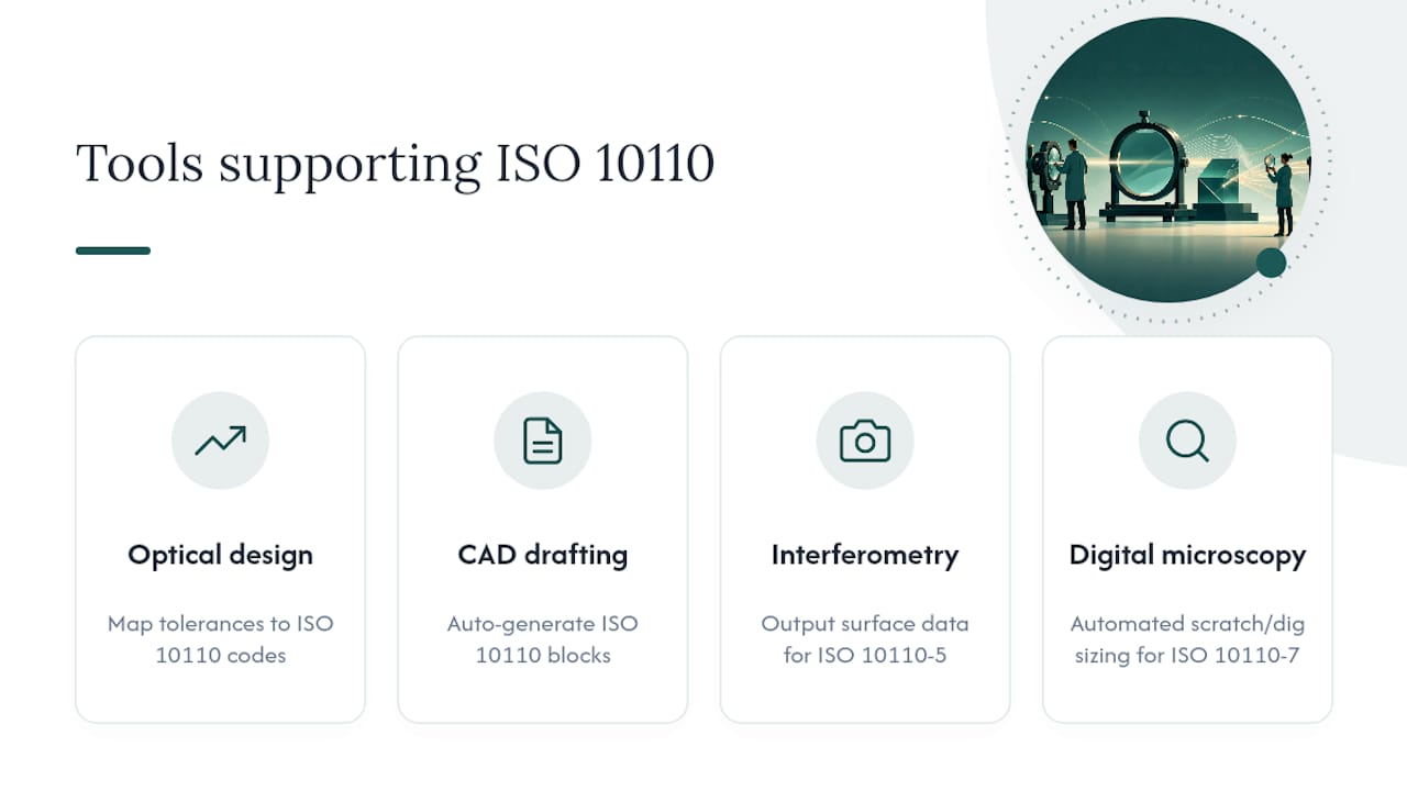
Modern optical design software, including Zemax OpticStudio and Synopsys CODE V, allows engineers to model tolerances that map directly onto ISO 10110 codes, letting you simulate how a given 3/ or 0/ tolerance actually affects system performance before it reaches a drawing. This tolerance analysis capability helps justify why a tighter or looser code is appropriate for a given design, rather than defaulting to whatever tolerance a previous project happened to use.
CAD platforms with dedicated optical drafting extensions can generate the tabular format block automatically from a tolerance dataset, reducing the transcription errors that creep in when someone manually retypes codes from a specification sheet into a drawing template. Interferometry software from manufacturers like Zygo and 4D Technology outputs surface form data in formats that align directly with the fringe based notation used in ISO 10110-5 callouts, closing the loop between measurement and specification.
For surface imperfection inspection under the ISO 10110-7 dimensional method, digital microscopy systems paired with automated defect sizing software can measure and log scratch and dig areas far faster than manual visual grading, which matters given the additional measurement time this method demands compared with older visibility based approaches.
None of this software replaces engineering judgement about which tolerance actually matters for a given application. It simply removes the manual transcription and measurement bottlenecks that used to make full ISO 10110 compliance slower than it needed to be, and Precision Glasses’ own quality assurance processes build on exactly this combination of measurement software and disciplined documentation.
What Precision Glasses would tell you to prioritise first
Most guidance on ISO 10110 treats the notation system as the hard part, and it isn’t. Once you’ve worked through a handful of 3/ and 5/ codes with real numbers attached, the grammar sticks. The genuinely difficult part is the discipline of stating test conditions, and that’s the piece conventional advice tends to skip over.
I’d argue the tabular format matters less because it looks tidy and more because it forces you to fill in fields you’d otherwise leave implicit. A scattered note might say 3/2 and stop there. A table forces you to also state the wavelength, the method, and the edition, and it’s precisely those omitted details that cause first article rejections months later.
If you’re specifying optics for the first time under this standard, don’t start by memorising every code. Start by deciding, part by part, whether you actually need the dimensional rigour of ISO 10110-7 or whether a legacy visibility grade still serves your application. That single decision shapes your inspection budget more than any amount of notation fluency ever will. Get that right, and the codes themselves become straightforward.
— Alexandra
Sources
Start with the primary documents rather than secondary summaries when precision matters. ISO 10110-1:2019 is the anchor text for layout and tabular format rules, and the ISO 10110-5:2026 edition covers the current surface form tolerance rules.
For worked interpretation, Modern Optics Drawings: The ISO 10110 Companion walks through example drawings code by code, which is invaluable when you’re training junior engineers on the notation.
- ISO 10110-1:2019 – Optics and photonics — Preparation of drawings for optical elements and systems — Part 1: General
- 9102 First Article Inspection Requirement – IAQG
Keep template drawings on hand once you’ve built a compliant tabular block. Reusing a validated table structure across projects prevents the format drift that creeps in when every engineer builds their own version from memory.


