
Specify a UV sensor window as a tested optical element, not a protective cover. Match substrate transmission to your sensor’s actual working band, set a transmitted wavefront target measured in the assembled state, and bring a precision glass supplier into the conversation before you finalise the mechanical envelope. Get those three decisions right early, and everything downstream, coatings, mounting, acceptance testing, gets considerably simpler.
TL;DR:
- Matching substrate transmission to the sensor’s operating band is crucial, with fused silica suitable for most UV to visible applications and low-OH grades needed for deep UV.
- Optical performance depends on transmitted wavefront error, with specifications like λ/15 rms at 632.8 nanometres necessary for high-resolution imaging systems.
- Mounting stress can significantly distort wavefronts, so measuring wavefront error in the mounted state is essential to ensure performance.
- Coating and environmental testing should be quantified with clear passing criteria at multiple fabrication stages to verify durability and optical stability.
- Certify laser or military-grade standards like AS9100, ISO 9001, or MIL-STD-810, and share detailed mechanical and environmental requirements early in procurement.
Table of Contents
- Material and transmission tradeoffs for UV sensor windows
- What optical tolerances actually matter for a UV window?
- How does mounting affect optical performance?
- Coatings, environmental durability and verification
- Recommended testing and quality control after fabrication
- Interfacing UV sensor windows with OEM instrument designs
- What certifications matter for OEM UV window procurement?
- How long does custom UV window fabrication take?
- Engineer’s viewpoint: what actually goes wrong
- How Precision Glasses supports UV sensor window procurement
- Sources
Material and transmission tradeoffs for UV sensor windows
Every material decision for a UV window comes down to a trade between spectral reach and mechanical resilience, and the sensor’s operating band should decide that trade before cost does.
Fused silica remains the default substrate for many UV to visible sensor applications. It transmits well from roughly 185 to 2,500 nanometres, depending on grade, and offers good dimensional stability at a manageable cost. If your application pushes into deep UV, below 200 nanometres, hydroxyl content in the glass matters. Higher purity, low OH grades reduce absorption losses that standard fused silica exhibits at shorter wavelengths, so specify grade explicitly rather than leaving it to the supplier’s default stock.
Sapphire extends transmission further, covering roughly 170 to 5,500 nanometres, and its real advantage isn’t optical at all. It’s mechanically formidable: high hardness, strong resistance to abrasion and impact, and better thermal shock tolerance than silica. Choose sapphire when the window faces pressure differentials, particulate erosion, or handling risk in the field, not purely because the transmission curve looks marginally better on paper.
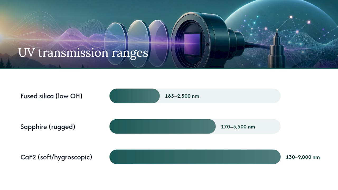
Calcium fluoride (CaF2) reaches the widest span of the three, from around 130 to 9,000 nanometres, making it the material of choice for excimer laser systems and deep UV instrumentation. That reach comes at a cost: CaF2 is mechanically soft, prone to cleaving under stress, and hygroscopic enough that ambient humidity can degrade its surface over time. It demands careful handling, protective coatings, and usually a controlled environment.
A few points that catch procurement teams out:
- Engineering plastics and acrylics have no place in precision UV sensor windows; they yellow, craze, and lose transmission under UV exposure within months.
- Coating chemistry interacts with substrate choice. An AR stack optimised for silica won’t necessarily perform the same way on sapphire or CaF2.
- If your optical path includes a coherent source, wedged or Brewster-angle geometries solve etalon fringing or polarisation loss that a flat window cannot.
Detailed spectral curves and mechanical data for each substrate are worth reviewing against your own material selection guidance before you commit to a drawing revision.
What optical tolerances actually matter for a UV window?
Aperture and thickness alone tell a supplier almost nothing about how a window will perform once it’s bonded into your instrument. The specification that actually governs performance is transmitted wavefront error, sometimes called transmitted wavefront deformation (TWD), because it captures how much the window distorts light passing through it under real operating conditions.
Four parameters do the real work:
- Clear aperture — the usable optical zone, distinct from the physical part size, and it should account for mounting shadow.
- Surface figure — expressed as peak-to-valley or RMS deviation from the ideal shape, usually specified per surface.
- Transmitted wavefront error (WFE/TWD) — the cumulative distortion light experiences passing through the finished, mounted window.
- Surface quality (scratch/dig) and spectral transmission curve — cosmetic and functional limits that affect stray light and signal-to-noise.
Airborne electro-optical camera systems have specified transmitted wavefront deformation as tight as λ/15 rms at 632.8 nanometres, a benchmark that reflects how sensitive high-resolution imaging systems are to even modest wavefront distortion. A window that meets that figure preserves image resolution and alignment tolerance across the whole optical train; one that doesn’t introduce blur or pointing error that no amount of downstream signal processing fully corrects.
One documented dual-band window project measured manufacturing WFE at 39.2 nanometres RMS and post-assembly WFE at 44.3 nanometres RMS, comparing both against simulated predictions to trace exactly where distortion crept in during fabrication and integration, as recorded in the project’s published measurements. That kind of staged verification, measuring at multiple build points rather than trusting a single final check, is what separates a window that performs in the lab from one that performs in the field.
When you send out a request for quote, ask for interferograms at relevant build stages, a spectral transmission graph across your working band, and written acceptance criteria tied to numbers, not adjectives like “good” or “high quality.”
Pro Tip: Don’t lock your WFE allocation before your supplier has seen the mounting design. Iterate the number with them once, and you’ll usually avoid a costly second round of tooling later.
How does mounting affect optical performance?
The window doesn’t distort in isolation. It distorts once you clamp it, bolt it, or bond it into a housing, and that’s exactly why measuring optical figure on an unmounted part tells you very little about how the assembly will actually behave.
Three mounting approaches dominate OEM instrument design, each with a different stress profile:
- Bonded mounts offer good sealing and vibration resistance but introduce stress from adhesive cure shrinkage and any CTE mismatch between the glass and the housing material.
- Bolted or gasketed mounts allow field serviceability and easier replacement but concentrate load at discrete points unless clamp force is carefully controlled.
- Clamped mounts distribute load more evenly but need groove geometry that avoids point contact against the glass edge.
Experts in the optical protective window field emphasise assembly-state evaluation for exactly this reason: measuring the finished, mounted part captures the stress-induced wavefront error that a bench measurement on a bare blank simply misses. A window can pass every spec sheet unmounted and still fail once torqued into its housing.
Practical steps that reduce iteration risk:
- Specify mounting groove radius and clamp force limits on the drawing, not verbally.
- Provide CTE data for the housing material so the fabricator can flag mismatch risk before bonding, particularly for thermal cycling applications.
- Require WFE measurement in the mounted state as a contractual deliverable, not an optional extra.
- Run a basic deflection check against expected pressure or vibration loads before finalising thickness, since undersized windows flex measurably under differential pressure.
Pro Tip: Send your fabricator the full assembly drawing, not just the window callout. Stress sources are almost always in the interface, not the glass itself.
Our optical fabrication guide covers interferometric testing methods relevant to verifying mounted assemblies in more depth.
Coatings, environmental durability and verification
Coating choice changes both optical performance and how long that performance lasts in service.
- AR coatings for UV reduce Fresnel losses at each surface; get numeric reflectance targets in writing, not a general claim of “low reflection.”
- Protective hard coats guard against abrasion during cleaning and handling, particularly important for CaF2’s soft, hygroscopic surface.
- Hydrophobic treatments reduce soiling and water spotting but can be more easily abraded under mechanical cleaning, so weigh the cleaning regime the window will actually see in service.
Environmental verification should include spectral transmission checks before and after exposure, adhesion testing on the coating stack, abrasion cycling, thermal cycling matched to your deployment range, and salt fog testing if the instrument operates in marine or coastal environments. Write acceptance criteria as numbers, minimum transmission at a stated wavelength after N thermal cycles, rather than a pass/fail judgement call. Our coatings and testing overview details typical test protocols worth referencing in a purchase specification.
Recommended testing and quality control after fabrication
Verification should happen at more than one stage, not just at final inspection. Measure the window blank after polishing, again after coating, and once more after full assembly into its mount, comparing each stage against simulated predictions to trace exactly where distortion enters the part.
A defensible QC sequence includes:
- Interferometric wavefront measurement at each build stage, referenced against the design prediction.
- Spectral transmission testing across the sensor’s working band, using the actual coated part rather than a witness sample alone.
- Dimensional and surface quality inspection against the drawing’s clear aperture, wedge, and scratch/dig callouts.
- Environmental stress testing appropriate to deployment, thermal cycling, vibration, or salt fog, followed by a repeat optical check to confirm nothing shifted.
This staged approach mirrors the practice used on documented airborne camera window projects, where manufacturing and assembly WFE were measured separately and cross-checked against simulation rather than accepted on a single final reading. Ask your supplier for the raw interferogram data at each stage, not just a summary pass/fail sheet. Data you can review yourself is worth far more during a design review than a certificate stating conformance.
Interfacing UV sensor windows with OEM instrument designs
Sealing and adjacent-component compatibility decide whether a window that performs beautifully on the bench keeps performing once it’s living inside your instrument housing.
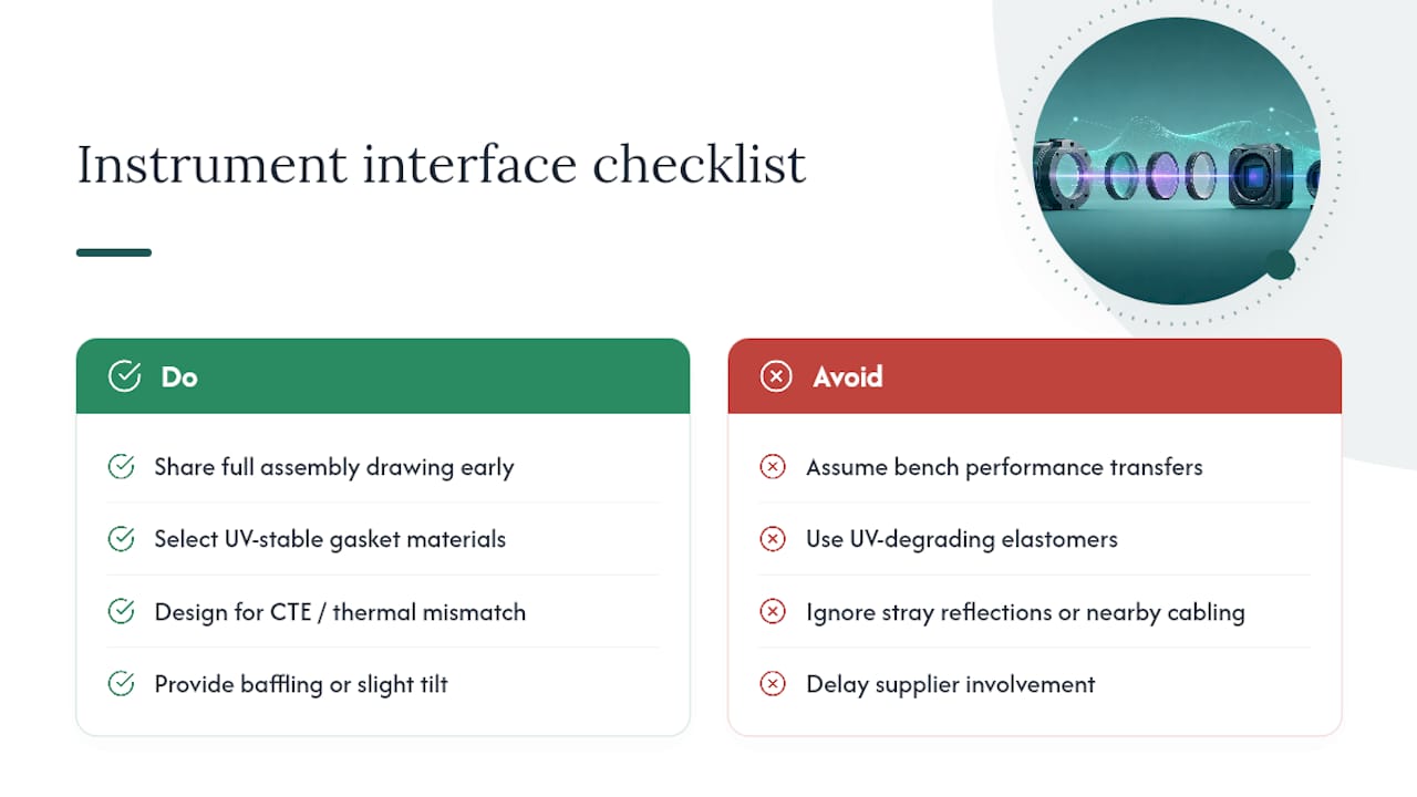
Sealing choices need to account for the UV exposure itself. Some elastomer seals degrade under sustained UV, so gasket material selection deserves the same scrutiny as the glass. Where the housing uses a different material, aluminium against fused silica, for instance, thermal expansion mismatch across the operating temperature range can load the bond line and shift the wavefront exactly as described in the mounting section above.
Feedthroughs and adjacent electronics add their own constraints. If the window sits near a sensor’s active detection surface, stray reflections off the housing interior can degrade signal-to-noise even when the window itself transmits cleanly, so consider baffling or a slight tilt in the mounting geometry. Where cabling or gas lines need to pass near the optical path, a drilled window geometry can solve that without compromising the sealed aperture.
Share your full instrument assembly drawing with the glass fabricator early, not just the window’s own dimensional callout. A supplier who can see the housing, the gasket groove, and the neighbouring components can flag interface risks, CTE mismatch, seal compatibility, clamp load, before they become expensive rework. Our electronics procurement guide walks through this handoff in more practical detail for teams sourcing display and sensor glass alongside window components.
What certifications matter for OEM UV window procurement?
Compliance requirements for UV sensor windows track the end application rather than the glass itself, so the certification that matters depends heavily on which sector you’re supplying.
Defence and aerospace programmes typically require batch-level material traceability and documented process control, often under quality management frameworks such as AS9100 for aerospace suppliers or ISO 9001 as a general manufacturing baseline. Medical device applications bring their own regulatory layer, where the window may need to be qualified as part of a device under ISO 13485-aligned quality systems, with documented biocompatibility if the glass contacts tissue or fluids.
Environmental and durability testing standards, thermal cycling, humidity, salt fog, often reference military or industrial test method standards such as MIL-STD-810 for equipment intended for harsh deployment. None of these certifications substitute for the optical specification itself; a window can be fully compliant on paperwork and still underperform if clear aperture, WFE, and coating targets weren’t nailed down in the same purchase order.
Ask any prospective supplier for their quality management certification and batch traceability process before sending a drawing. A fabricator who can show consistent, documented process control across production runs is the one who can actually hold your WFE target run after run, not just on the first sample.
How long does custom UV window fabrication take?
Lead time for a custom UV sensor window depends heavily on substrate, coating complexity, and how tight the optical tolerance is, but a few patterns hold across most OEM projects.
Fused silica parts with standard AR coatings and moderate WFE targets tend to move fastest through fabrication, since the raw material is readily available and the polishing process is well established. Sapphire adds time because of its hardness; grinding and polishing take longer per part. CaF2 adds handling overhead because of its fragility and hygroscopic nature, and often needs to be processed and stored under controlled humidity right up to coating.
Coating stacks add their own queue. A single-layer AR coating runs faster than a multi-layer stack tuned for a specific UV band with a hard protective overcoat, and batch scheduling at the coating stage often depends on what else is in the chamber that week.
For procurement planning, get quotes with lead time broken out by stage, substrate procurement, fabrication, coating, and mounted-state verification, rather than a single bundled number. That breakdown tells you where a schedule risk actually sits if a project timeline compresses. It’s also worth asking early whether your quantity supports prototype-then-production staging, since a single prototype run with full interferometric verification before committing to volume tooling is often cheaper in the long run than discovering a WFE problem after fifty parts are already cut.
Engineer’s viewpoint: what actually goes wrong
The most common failure isn’t a bad material choice. It’s engaging the glass supplier after the mechanical design is frozen, then discovering the mounting geometry makes the WFE target unreachable. The second most common mistake is measuring optical figure only on the bare, unmounted blank and assuming the assembled part will match.
Fix both by sharing assembly drawings and mounting details at the same time as the optical spec, and by writing acceptance criteria as numbers, not descriptions. Vague terms like “high quality” or “good transmission” invite disputes at final inspection. The process should be treated iteratively, focusing on the window as a system-level component from the first conversation rather than a line item added late.
— Alexandra
How Precision Glasses supports UV sensor window procurement
Specifying a UV sensor window well means having a supplier who treats the mounted assembly, not just the raw blank, as the thing being measured. Precision Glasses works across fused silica, sapphire, and CaF2 substrates, applies AR and protective coating stacks suited to UV bands, and verifies wavefront error and spectral transmission at multiple build stages rather than relying on a single final check.

For procurement teams ready to move a specification forward, the fastest route is preparing three things before the first call: your sensor’s spectral sensitivity curve, mechanical drawings showing the full mounting interface, and your target environmental conditions. From there, requesting a sample part with an accompanying interferogram gives your engineering team something concrete to review against the design prediction, rather than a spec sheet on trust alone. Visit Precision Glasses to start that conversation, or explore sector-specific capabilities if your project sits in defence, aerospace, or medical instrumentation.
Sources
- Optical protective window design and material selection issues in multi‑sensor electro‑optical surveillance systems
- Dual band optical window (DBW) for use on an EO/IR airborne camera


