
Glass tolerances are defined as the permissible limits of dimensional and visual variation in a glass component that allow it to function correctly and be manufactured reliably. Every precision glass part, whether destined for aerospace optics, medical devices, or automotive dashboards, carries a set of tolerance specifications that determine whether it performs or fails. Understanding those specifications is not optional for engineers. It is the foundation of every sound design decision. This guide covers glass tolerance definitions, the standards that govern them, how manufacturing processes shape what is achievable, and how sensitivity analysis helps you specify tolerances that are tight enough to work and realistic enough to produce.
What is the explanation of glass tolerances?
Glass tolerances are the formally specified boundaries within which a manufactured glass component must fall to be accepted. The industry distinguishes between dimensional tolerances, which govern physical geometry, and visual or optical tolerances, which govern surface and distortion characteristics. Both categories appear in standards such as ASTM C1048, DIN 7080, and ASTM D1000-22, and both directly affect whether a component fits its assembly and performs its function.
The term “glass tolerance” covers several distinct metrics. Thickness tolerance defines how much a panel or disc may vary from its nominal thickness. Length and width tolerances set the acceptable deviation in planar dimensions. Edge quality tolerances specify the maximum permissible chip size along cut edges. Surface finish tolerances address roughness and flatness. Each metric is measured in millimetres or micrometres, and each carries different consequences if exceeded.

For engineers in defence, aerospace, or medical device sectors, a missed tolerance is rarely a cosmetic issue. A borosilicate sight glass disc specified under DIN 7080 that falls outside its diameter-to-thickness ratio will fail its pressure rating under operating conditions. A heat-treated panel that meets ASTM C1048 bow limits but exhibits excessive roller wave will distort imagery in an optical system. The distinction between compliance and true functional performance is where experienced engineers focus their attention.
What types of glass tolerances do engineers need to know?
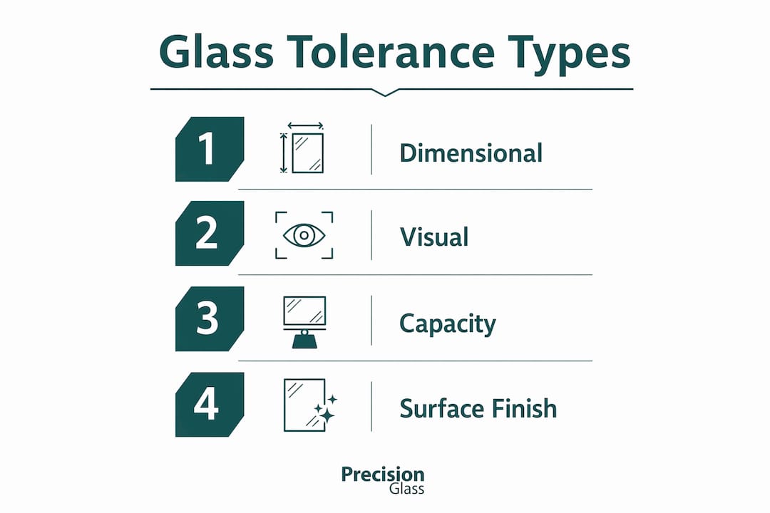
Glass manufacturing tolerances divide into four primary categories. Understanding each one allows you to write specifications that are complete, unambiguous, and manufacturable.
Dimensional tolerances cover the physical geometry of the component:
- Thickness tolerance: Typically expressed in ±mm or ±µm. Precision laser cutting can achieve thickness consistency to within ±0.005 mm for thin optical substrates.
- Length and width tolerance: Governed by the cutting method. Femtosecond laser processes hold ±0.005 mm; conventional CO2 laser processes hold ±0.05 mm.
- Edge chip size: Femtosecond laser cutting produces edge chips below 5 µm, while CO2 laser cutting produces chips in the 50–200 µm range. For optical assemblies, chip size directly affects seal integrity and stray light.
- Kerf width: The material removed during cutting affects final part dimensions and must be accounted for in CAD drawings.
Capacity tolerances apply to glass containers and vessels. Under ASTM D1000-22, a 1 L glass bottle carries a volume tolerance of ±1.1%, corresponding to a fill range of 989–1,011 mL. Continuous-thread closures achieve 0.2–0.3% tighter control than lug or snap-on finishes. Smaller vessels show proportionally larger wall thickness inconsistencies, while larger jars are more susceptible to thermal distortion effects during forming.
Visual and optical tolerances address distortion in heat-treated glass. ASTM C1048 defines three distortion types: roller wave, edge lift, and bow. Roller wave is periodic surface waviness introduced by the roller furnace. Edge lift results from faster cooling at the glass perimeter. Bow is the overall curvature of the panel. Each affects optical and visual performance differently, and each requires separate measurement and specification.
Surface finish tolerances define roughness in µm Ra and are critical for optical components where scatter and transmission losses must be minimised.
How do manufacturing processes affect achievable tolerances?
The fabrication method you select determines the tolerance range you can realistically specify. No single process suits every glass type or application.
| Process | Dimensional Tolerance | Edge Chip Size | Best For | Cost Level |
|---|---|---|---|---|
| Femtosecond laser | ±0.005 mm | <5 µm | Sapphire, thin optical glass | High |
| Picosecond laser | ±0.01 mm | 5–20 µm | Borosilicate, precision parts | High |
| UV nanosecond laser | ±0.02 mm | 20–50 µm | General precision glass | Medium |
| CO2 laser | ±0.05 mm | 50–200 µm | Thick soda-lime, display glass | Low–Medium |
| Diamond CNC machining | ±0.01 mm | Polished finish | 3D features, complex geometry | Medium–High |
| Waterjet cutting | ±0.1 mm | Variable | Thick structural glass | Low |
| Score and break | ±0.2 mm | Variable | High-volume flat glass | Low |
Ultrafast laser processes, specifically femtosecond and picosecond systems, achieve micron-level tolerances by delivering energy faster than the glass lattice can conduct heat. This prevents thermal cracking and produces clean, stress-free edges. The trade-off is cost and throughput. Diamond CNC machining offers ±0.01 mm with a polished finish and the ability to produce three-dimensional features such as chamfers and counterbores, but it is slower than laser processes for thin parts.
Matching the glass type to the correct process is not optional. Sapphire and tempered glass require ultrafast laser cutting to achieve acceptable edge quality. Attempting to score and break tempered glass destroys the component. Borosilicate is more process-flexible, but high-frequency or optical applications still demand ultrafast methods to hold the required tolerances.
Pro Tip: When specifying tolerances for borosilicate or sapphire components, confirm with your fabricator which laser system they will use before finalising drawings. The difference between a femtosecond and a CO2 process is a tenfold change in achievable dimensional tolerance.
You can review how modern glass fabrication methods map to specific tolerance requirements in the Precision Glasses fabrication guide.
What standards govern glass tolerance specifications?
Industry standards provide the baseline framework for specifying and verifying glass tolerances. They are the starting point, not the complete answer.
The most widely referenced standards for engineers working with flat and heat-treated glass include:
- ASTM C1048: Covers heat-treated flat glass, including tempered and heat-strengthened types. Specifies bow, warp, and edge tolerances. Critically, ASTM C1048 does not fully address roller wave or edge lift, meaning a panel can pass ASTM bow limits and still exhibit unacceptable optical distortion in practice.
- DIN 7080: Governs borosilicate 3.3 glass for sight glass discs used in process vessels and pipework. Pressure ratings under DIN 7080 depend on the diameter-to-thickness ratio of the disc, not on material grade alone. Specifying the wrong ratio for a given operating pressure is a safety-critical error.
- ASTM D1000-22: Applies to glass container capacity tolerances. Useful for pharmaceutical and chemical packaging applications where fill volume accuracy is a regulatory requirement.
The limitation of all three standards is the same. They define minimum compliance thresholds for common applications. Advanced optical systems, defence optics, and medical imaging components routinely require specifications that go beyond what any published standard mandates. In those cases, fabricator-specific tolerance sheets, agreed visual mockups, and written acceptance criteria become the governing documents.
Pro Tip: Always request your fabricator’s internal tolerance capability sheet alongside the relevant standard. The standard tells you the minimum; the capability sheet tells you what is actually achievable on their equipment.
For a structured overview of how ASTM C1048, DIN 7080, and related standards apply across manufacturing contexts, the Precision Glasses quality standards guide provides detailed sector-specific guidance.
How should engineers apply tolerance analysis to glass specifications?
Sensitivity and tolerance analysis is the structured process of identifying which parameters most affect system performance and quantifying how much variation each can tolerate before the system fails its requirements. For glass components, the parameters typically include thickness, bow, refractive index, surface flatness, and edge quality.
The process follows a logical sequence:
- Identify critical parameters. List every glass characteristic that affects the function of the assembly. For an optical system, this includes refractive index uniformity, surface figure, and transmitted wavefront error. For a structural application, it includes thickness, edge chip size, and flatness.
- Assign sensitivity values. Determine how much each parameter shifts system performance per unit of variation. A 10 µm change in thickness may be negligible for a structural panel but critical for an interferometric component.
- Set tolerance budgets. Allocate permissible variation to each parameter based on its sensitivity. Parameters with high sensitivity receive tight tolerances. Parameters with low sensitivity receive relaxed tolerances. This prevents over-specification, which drives cost without improving performance.
- Predict manufacturing yield. Use the tolerance budgets to estimate what percentage of parts will fall within specification given the process capability of your chosen fabrication method. Tolerance analysis predicts spec compliance rates and guides decisions on whether to tighten the process or relax the specification.
- Integrate into DFM review. Bring tolerance decisions into the design for manufacturability review before drawings are released. DFM reviews resolve risks such as edge polishing grades, hole locations, and minimum web thicknesses before they become production rejects.
The most common error engineers make is specifying uniform tight tolerances across all parameters to be safe. This approach increases cost significantly and often does not improve functional performance. Sensitivity analysis is the tool that separates the tolerances that matter from those that do not.
Pro Tip: Treat tolerance analysis as a design decision tool, not a documentation exercise. Run it before you finalise drawings, not after. Changes at the drawing stage cost almost nothing. Changes after first article inspection cost considerably more.
A thorough walkthrough of how to structure this process is available in the Precision Glasses glass component design guide.
Key takeaways
Specifying glass tolerances correctly requires matching dimensional limits, visual distortion criteria, and manufacturing process capabilities to the functional demands of the application.
| Point | Details |
|---|---|
| Tolerance types are distinct | Dimensional, visual, capacity, and surface finish tolerances each require separate specification and measurement. |
| Process determines capability | Femtosecond lasers achieve ±0.005 mm; CO2 lasers achieve ±0.05 mm. Choose the process before finalising drawings. |
| Standards set the floor | ASTM C1048 and DIN 7080 define minimum compliance but do not cover all optical distortion or pressure-rating nuances. |
| Sensitivity analysis prevents over-specification | Assign tight tolerances only to parameters with high sensitivity to system performance. |
| DFM reviews reduce cost | Resolving tolerance risks before production starts avoids expensive post-production rejects. |
Why tolerance decisions belong at the design table, not the inspection stage
My experience working with engineers across defence, aerospace, and medical device programmes has taught me one consistent lesson: tolerance problems are almost always design problems in disguise. By the time a component fails incoming inspection, the costly decision has already been made, usually weeks earlier when someone wrote a tolerance on a drawing without checking whether any fabricator could actually hold it.
The shift I have seen make the greatest difference is treating glass tolerance specification as a collaborative act. Bring your fabricator into the conversation at the concept stage. Share your functional requirements, not just your dimensional targets. A good fabricator will tell you whether your ±0.01 mm flatness requirement is achievable on their grinding equipment or whether it requires a lapping step that doubles the lead time. That conversation, held early, saves money and prevents schedule risk.
The other pitfall I see regularly is the assumption that tighter is always better. It is not. A tolerance tighter than the application demands adds cost, reduces yield, and sometimes introduces residual stress from over-processing. Sensitivity analysis is the antidote. When you can show that a ±0.05 mm thickness variation has no measurable effect on your optical path length, you have a defensible reason to relax that tolerance and reduce your unit cost. That is not compromise. That is good engineering.
The technologies available today, particularly ultrafast laser systems and diamond CNC machining, have genuinely expanded what is achievable. But the best fabrication capability in the world cannot compensate for a specification that was written without understanding the process. The engineers who get the best results are the ones who understand both sides of that equation.
— Alexandra
Precision glasses: your partner for tight-tolerance glass components
When your application demands glass components that must perform to exacting specifications, the fabricator you choose determines whether your design succeeds in production.

Precision Glasses supplies precision-engineered glass components to defence, aerospace, medical device, automotive, and electronics sectors. Our capabilities span femtosecond and CO2 laser cutting, diamond CNC machining, grinding, polishing, and toughening, covering the full range of technical glass solutions your programme may require. We work with engineers from the design stage through to delivery, providing DFM input, tolerance capability data, and quality assurance documentation at every step. Explore our full range of precision glass services to find the right solution for your application.
FAQ
What are glass tolerances in manufacturing?
Glass tolerances are the specified limits of acceptable dimensional and visual variation in a manufactured glass component. They cover thickness, length, width, edge quality, flatness, and distortion, and are expressed in millimetres or micrometres.
Which standard governs heat-treated glass tolerances?
ASTM C1048 is the primary standard for heat-treated flat glass, covering bow, warp, and edge tolerances. It does not fully address roller wave or edge lift, so fabricator-specific criteria are often required for optical applications.
How tight a tolerance can laser cutting achieve?
Femtosecond laser cutting achieves dimensional tolerances of ±0.005 mm with edge chips below 5 µm. CO2 laser cutting achieves ±0.05 mm with chips in the 50–200 µm range.
What is sensitivity analysis in glass tolerance specification?
Sensitivity analysis identifies which glass parameters, such as thickness, bow, or refractive index, most affect system performance. It guides engineers to assign tight tolerances only where they matter, reducing cost without compromising function.
Why do glass tolerances sometimes need to exceed published standards?
Published standards such as ASTM C1048 define minimum compliance thresholds for general applications. Advanced optical, defence, and medical applications require tighter limits on roller wave, edge lift, and surface figure that standards do not mandate, making fabricator-specific specifications necessary.