Material selection rarely gets the attention it deserves early in sensor design. Yet the choice of glass is one of the most consequential decisions a product engineer can make. What is glass for sensors, precisely? It is a precision-engineered optical and structural material that governs how accurately a sensor detects, transmits, and interprets signals. Not all glass performs equally. The wrong specification introduces noise, false positives, thermal failures, and expensive recalibrations. The right glass, specified with full understanding of its optical, mechanical, and thermal properties, becomes an invisible enabler of sensor performance.
Table of Contents
- Key takeaways
- Properties that make glass suitable for sensors
- Design considerations for automotive and industrial sensors
- Challenges and innovations in sensor glass
- Selecting the right glass for your sensor project
- My perspective on glass in sensor development
- Precision glass solutions for sensor applications
- FAQ
Key takeaways
| Point | Details |
|---|---|
| Glass is a functional component | It directly affects signal quality, not just mechanical protection, in every sensor type. |
| Wavelength matching matters | Select glass based on transmission characteristics aligned to your sensor’s operating wavelength. |
| Thermal design is non-negotiable | Mismatched thermal expansion between glass and mounting hardware causes cracking and calibration loss. |
| Coatings amplify performance | Anti-reflective and low-emissivity coatings significantly improve signal penetration and reduce noise. |
| Precision fabrication determines accuracy | Glass thickness, flatness, and parallelism must be held to tight tolerances in ToF and LiDAR applications. |
Properties that make glass suitable for sensors
The role of glass in sensor technology is grounded in a specific set of physical and optical characteristics that no polymer substitute fully replicates.
Optical clarity and spectral transmission are the most critical starting points. Standard soda-lime glass transmits visible wavelengths well, but many sensors operate in the near-infrared range. Glass with low iron content achieves high visible transmittance and reduces light absorption, which is critical for infrared sensors where even modest attenuation introduces measurement error. Surface texture and cleanliness compound this: contaminated or rough glass produces roll-wave distortion and degrades infrared transmission directly.
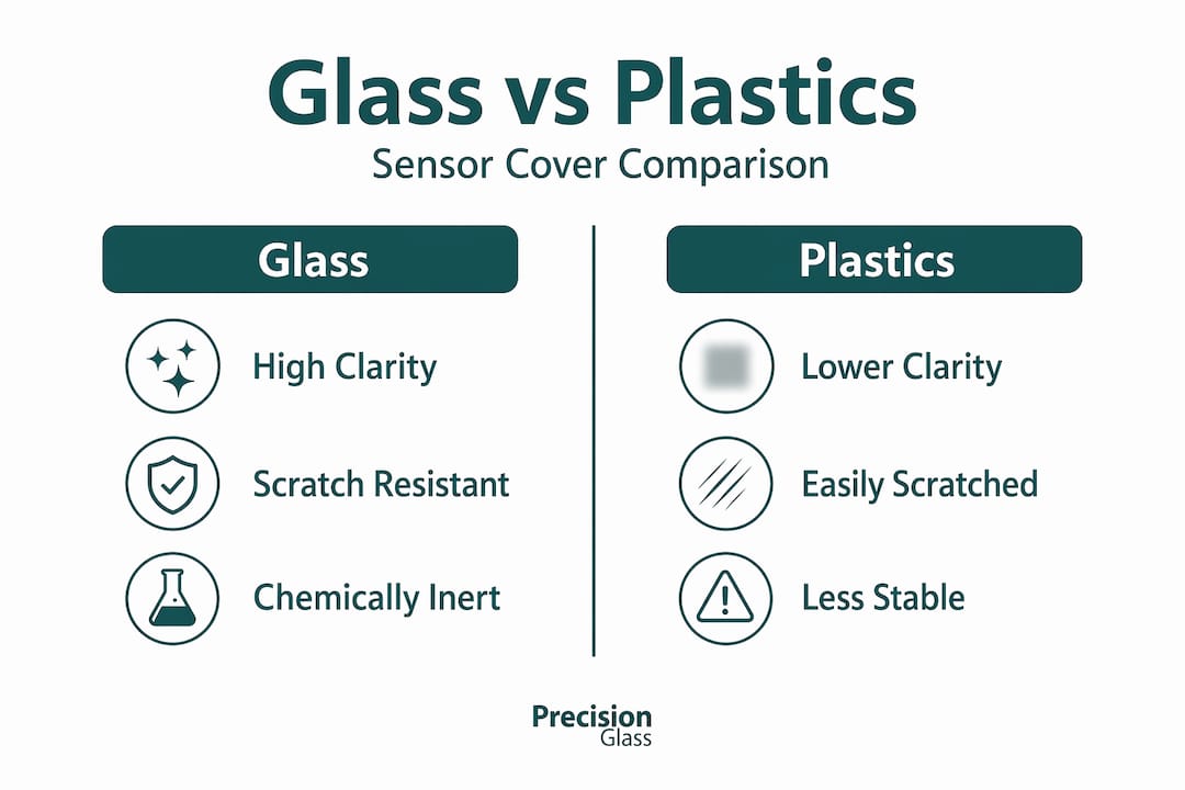
Dimensional stability under thermal cycling and mechanical load is another reason engineers choose glass for sensors over alternatives such as acrylic or polycarbonate. Glass maintains its geometry reliably across a wide temperature range. Acrylic softens above 80°C and exhibits birefringence under stress. Polycarbonate scratches easily and yellows under UV exposure. Both absorb moisture and change dimensionally over time. Glass does none of these things.
Scratch resistance and surface smoothness matter in sensing applications because surface defects scatter incident light. A polished glass surface holds sub-micron flatness tolerances that are practically impossible to achieve in moulded thermoplastics.
Chemical inertness makes glass the preferred choice in medical and industrial sensor housings where cleaning agents, sterilisation cycles, or process chemicals would degrade a polymer cover within months.
The table below summarises the key property comparisons for common sensor cover materials:
| Property | Borosilicate glass | Soda-lime glass | Acrylic | Polycarbonate |
|---|---|---|---|---|
| NIR transmission | Excellent | Good | Poor | Moderate |
| Thermal stability | Excellent | Good | Poor | Moderate |
| Scratch resistance | High | High | Low | Low |
| Chemical inertness | Excellent | Good | Moderate | Poor |
| Dimensional stability | Excellent | Good | Poor | Moderate |
Exploring the full range of engineered glass types available for precision applications helps clarify which substrate best suits your sensor’s operating conditions before you commit to a specification.
Pro Tip: Match your glass selection to the sensor’s primary operating wavelength. A LiDAR sensor at 905 nm requires very different glass transmission characteristics than a thermal imaging sensor at 8–14 µm. Verify spectral transmission data from the manufacturer, not just datasheet summaries.
Design considerations for automotive and industrial sensors
The uses of glass in sensors become most exacting in automotive and industrial contexts, where performance tolerances are tight and failure has real consequences.
LiDAR sensors demand near-complete transparency in the near-infrared band. Wideye glass transmits nearly 100% of near-infrared light, enabling LiDAR sensor precision whilst providing impact resistance and environmental protection. This is achieved through high-strength soda-lime glass with anti-reflective coatings precisely matched to LiDAR wavelengths. Standard glazing glass simply cannot deliver this level of spectral specificity.
Time-of-Flight sensors present a distinct challenge. Crosstalk caused by internal reflections within the cover glass causes false readings unless the glass is under 1 mm thick, perfectly parallel, and positioned very close to the emitter. These tolerances eliminate most off-the-shelf glass options entirely. The air gap between the glass and the sensor face is not a design convenience. It is a crosstalk management parameter.
Thermal expansion mismatches are a failure mode that is underestimated in early-stage sensor design. A mounting bracket that is too rigid cracks the glass under thermal cycling, whilst one that is too compliant allows the glass to shift and lose calibration, generating false positives. Thermal seal design must balance both risks simultaneously.
The table below shows how glass specifications align to common sensor types:
| Sensor type | Glass thickness | Parallelism tolerance | Key coating | Primary concern |
|---|---|---|---|---|
| LiDAR | 3–5 mm | ±0.05 mm | Anti-reflective (NIR) | NIR transmission loss |
| Time-of-Flight | <1 mm | ±0.01 mm | None or AR | Internal crosstalk |
| ADAS camera | 2–4 mm | ±0.05 mm | Low-E, anti-reflective | Optical distortion |
| Industrial proximity | 1–3 mm | ±0.02 mm | None | Dimensional stability |
The geometry of the glass also directly affects ADAS system calibration. Windshield replacements require calibration systems costing up to £15,000 to realign sensors correctly. This figure reflects how substantially glass curvature, thickness, and mounting angle influence where a sensor believes it is pointing. Glass geometry is not passive in sensor systems. It is a calibration input.
Pro Tip: When specifying glass for ADAS or LiDAR integration, request full spectral transmission curves from your supplier covering 700–1100 nm, not just visible-light transmittance values. A glass that looks optically clear to the eye may be attenuating your sensor signal by 15–20%.
Challenges and innovations in sensor glass
How does glass affect sensors when environmental conditions change? More significantly than most engineers plan for.
Condensation on sensor glass surfaces is a known problem in automotive applications. Water droplets on the outer face scatter laser pulses and degrade camera image quality precisely when reliable sensing is most needed. Solutions include hydrophobic coatings, heated glass elements, and integration of sensor housings that minimise moisture ingress. None of these are afterthoughts; they must be specified at the design stage.
Temperature variation creates expansion differentials between the glass, its coating, and its mounting frame. Thermal seals must be carefully engineered to absorb these stresses without transmitting them to the glass face or allowing positional drift. In practice, this means working with a glass fabricator who understands both the optical requirements and the mechanical boundary conditions simultaneously.
Recent industry advances are addressing these challenges on several fronts:
- Precision-ground glass with sub-micron surface flatness is now available for ToF sensor covers, eliminating the parallelism errors that previously forced designers to use expensive shimming processes.
- Glass-based substrates in semiconductor packaging deliver dimensional stability at high processing temperatures, enabling AI data centre chips where organic substrates fail under thermal load. This same stability is now being applied to sensor packaging in harsh industrial environments.
- Wavelength-selective coatings are becoming more accessible, allowing engineers to specify glass that passes a narrow NIR band whilst blocking ambient light, reducing sensor noise without additional electronic filtering.
- Sensor-integrated automotive glazing is currently focused on premium vehicles due to cost and technical precision requirements, but widespread LiDAR glass adoption is expected as LiDAR costs decrease across the automotive market.
Poor glass quality produces measurable, reproducible failures. Roll-wave distortion, surface contamination, and incorrect iron content all degrade NIR transmission in ways that are detectable in sensor output data but easily misattributed to electronics or firmware issues during development.
Selecting the right glass for your sensor project
Choosing glass materials for sensors requires a structured approach. The decisions made in specification directly affect prototyping outcomes, manufacturing yield, and field reliability.
- Define the sensor’s operating wavelength range first. Every other glass property decision flows from this. A 940 nm ToF sensor, a 1550 nm LiDAR system, and a broadband MEMS pressure sensor all require fundamentally different glass formulations.
- Specify surface flatness and parallelism as primary tolerances, not secondary. For ToF sensors, parallelism under 0.01 mm is not optional; it is the difference between accurate readings and crosstalk-induced noise. Consult the advanced glass specifications guide to understand which tolerances apply to your application.
- Evaluate coating requirements alongside the base glass. Anti-reflective coatings matched to your sensor wavelength can recover 4–8% of signal that would otherwise be lost to surface reflection. Specify the coating stack, not just the substrate.
- Prototype with the same fabrication process as production. CNC-ground and polished glass behaves differently from cut and lapped glass. Prototypes made from the wrong process will give misleading optical and mechanical data.
- Establish cleaning and handling protocols before testing begins. Surface contamination is the single most common source of unexplained sensor performance variation during development. Glass cleanliness must be controlled as carefully as its geometry.
- Select a fabricator with documented quality assurance processes for optical glass. Dimensional reports, spectral transmission verification, and surface quality inspection should be standard deliverables, not optional extras. Review the quality standards expected from a precision glass supplier before placing an order.
Common pitfalls include specifying standard architectural glass for sensor covers to save cost, failing to account for coating durability under cleaning cycles, and underestimating the effect of glass curvature on sensor field-of-view calculations.
My perspective on glass in sensor development
I’ve spent considerable time working with product development teams who treat the sensor cover glass as the last component they specify, essentially a transparent lid chosen primarily on cost. That mindset creates problems that surface late in development, when schedules are tight and root causes are hard to isolate.
What I’ve learned is that the glass interacts with every other element of the sensor optical system. Its refractive index shifts the effective focal plane. Its thickness alters the path length of the sensing beam. Its coating reflects or transmits selectively, changing the spectral content of what reaches the detector. When engineers ignore these effects early, they discover them during system integration, and fixing them at that stage is expensive.
The most counterintuitive lesson from experience is that better glass often makes the electronics simpler. When the optical path through the glass is clean and well-characterised, signal processing algorithms need less compensation, and the system is more robust across temperature and contamination conditions. Spending more on precision glass fabrication frequently reduces the firmware complexity needed to achieve the same accuracy target.
My strong advice is to bring your glass supplier into the design conversation at the component selection stage. Not after the housing is designed. The physical and optical properties of the glass should be an input to the housing geometry, not constrained by it. Teams that do this consistently produce better first prototypes and reach production faster.
— Alexandra
Precision glass solutions for sensor applications
At Glassprecision, we design and fabricate precision glass components specifically for demanding sensor applications across automotive, aerospace, medical, and defence sectors. Our components are specified, ground, polished, and coated to the tolerances your sensor design requires, whether that means sub-millimetre ToF cover glass, NIR-optimised LiDAR glazing, or chemically inert medical sensor substrates.
Every component we produce goes through documented quality assurance, including dimensional verification and spectral transmission testing where applicable. We work directly with your engineering team to align material selection, coating specification, and fabrication process to the performance targets that matter in your application. You can explore the full range of precision glass applications we support, or review the sectors we serve to see how we have delivered tailored glass solutions for programmes with similar technical requirements to yours. To discuss your sensor glass specification with our technical team, contact Glassprecision directly.
FAQ
What is glass for sensors and why does it matter?
Glass for sensors refers to precision-engineered glass components used as covers, substrates, or optical windows in sensing systems. It directly affects signal transmission, dimensional stability, and sensor accuracy, making material specification a critical engineering decision.
Why is glass preferred over plastic for sensor covers?
Glass outperforms polymer alternatives in NIR transmission, scratch resistance, dimensional stability, and chemical inertness. Acrylic and polycarbonate degrade thermally and absorb moisture, introducing dimensional changes that compromise sensor calibration over time.
How does glass thickness affect Time-of-Flight sensors?
For ToF sensors, cover glass must be under 1 mm thick and precisely parallel to control internal reflections. Crosstalk from thicker or imprecise glass causes erroneous distance readings that cannot be corrected in software alone.
What coatings are used on sensor glass?
Anti-reflective coatings matched to the sensor operating wavelength are the most common, recovering surface reflection losses and improving signal penetration. Low-emissivity and hydrophobic coatings are applied in automotive and outdoor sensor applications to manage thermal and environmental effects.
How does glass geometry affect ADAS sensor calibration?
Glass curvature, thickness, and mounting angle are all calibration inputs for ADAS systems. Incorrect geometry after a windshield replacement requires recalibration costing up to £15,000, illustrating how consequential glass specification is to long-term system performance.