

Glass has long been considered one of the most difficult materials to prototype. Where polymers and metals respond predictably to additive and subtractive processes, glass demands an entirely different level of thermal and material control. Yet what is glass prototyping, really? In industrial terms, it refers to the fabrication of functional or near-functional glass components using advanced manufacturing methods, including additive manufacturing, laser processing, and sol-gel techniques, prior to committing to full production. The field has matured considerably, and design freedom in glass AM is now achievable in ways that were simply not practical a decade ago.
Table of Contents
- Key takeaways
- Core glass prototyping methods
- Technical challenges in glass prototyping
- Applications of glass prototyping in engineering
- Workflow for custom glass prototyping
- Choosing the right prototyping method
- My perspective: what glass prototyping actually demands
- How Glassprecision supports your prototyping programme
- FAQ
Key takeaways
| Point | Details |
|---|---|
| Glass prototyping is a specialist discipline | It requires thermal, material, and process control far beyond standard polymer or metal prototyping. |
| Three primary methods exist | Molten extrusion, sol-gel ink printing, and laser processing each suit different precision and cost requirements. |
| Thermal control is the critical variable | Layer adhesion failures and residual stresses originate from temperature instability, not CAD errors. |
| Applications span demanding industries | Microfluidics, aerospace optics, defence components, and automotive sensors all benefit from glass prototyping. |
| Early manufacturer collaboration matters | Engaging a precision glass fabricator at the design stage prevents costly iterations and dimensional errors. |
Core glass prototyping methods
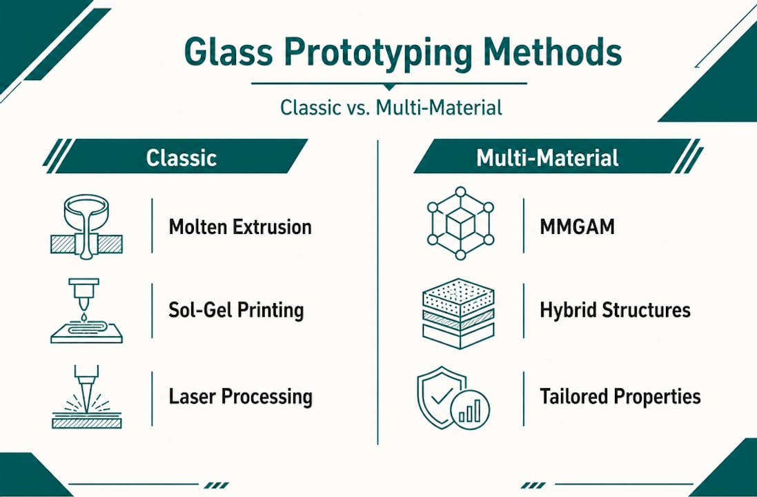
Glass additive manufacturing (glass AM) is the recognised industry term for the broader category that most engineers now describe colloquially as glass prototyping. It encompasses three distinct technical routes, each with its own physical principles and practical trade-offs.
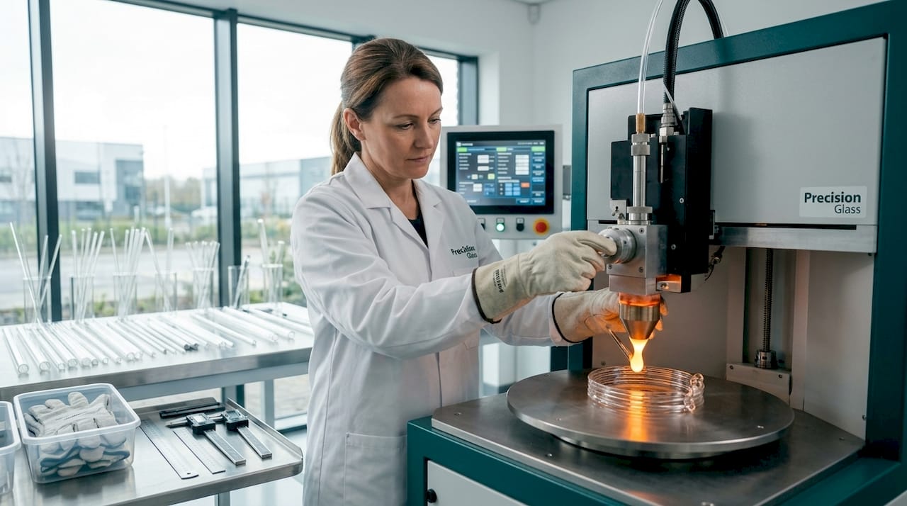
Molten glass extrusion deposits glass in a viscous state at temperatures between 1,000°C and 1,400°C. The material is extruded layer by layer, with thermal control critical to prevent adhesion failures between layers. Visible layer lines are a common artefact, and annealing is required after printing to relieve thermal stress and approach optical clarity. This method suits structural and semi-optical components where absolute surface perfection is not required from the outset.
Sol-gel ink printing takes a fundamentally different approach. A precursor ink, typically silica or silica-titania based, is deposited and then sintered at far lower temperatures than molten extrusion requires. Custom silica-titania inks enable optical index homogeneity, making this route particularly well suited to lenses and other precision optical components. The trade-off is added complexity in ink chemistry and careful management of drying and sintering parameters.
Laser-based processing operates differently again. Rather than building up material, it precisely removes or reshapes it. Laser manufacturing chains allow shaping, polishing, and form correction at nanometre tolerances. Fraunhofer ILT, for example, provides integrated laser-based workflows from feasibility study through to prototype and small-series production. This method excels when optical surface quality and dimensional accuracy are paramount.
A fourth and emerging category is multi-material glass additive manufacturing (MMGAM). By combining glass with polymers, metals, or ceramics, MMGAM enables multifunctional integrated architectures. Interfacial bonding and processing windows remain challenges, but the potential for integrated optical-electronic or optical-fluidic structures is considerable.
| Method | Resolution | Temperature demand | Optical quality | Best for |
|---|---|---|---|---|
| Molten extrusion | Moderate | Very high (1,000–1,400°C) | Moderate (post-processing needed) | Structural, semi-optical parts |
| Sol-gel ink printing | High | Moderate | High | Precision optics, lenses |
| Laser processing | Very high | Low (material removal) | Very high | Complex optics, form correction |
| MMGAM | Moderate | Variable | Variable | Multi-material integrated systems |
Pro Tip: If your prototype requires surface roughness below Ra 1 nm, laser-based processing is currently the only route that consistently achieves this without secondary grinding and polishing steps.
Technical challenges in glass prototyping
The gap between a convincing CAD model and a functional glass prototype is wider than in almost any other material category. Understanding why helps you plan realistic programmes.
The most common failure mode in extrusion-based glass prototyping is not a design error. It is thermal instability during deposition affecting layer bonding. Even small temperature variations during extrusion change the viscosity of the molten glass enough to prevent proper adhesion between successive layers, producing internal defects that are invisible until the component fails under load or optical inspection.
Residual stress is the second major concern. Glass does not deform plastically; it stores stress elastically until it fractures. Without a controlled annealing cycle after printing, prototypes are prone to spontaneous cracking, sometimes hours or days after fabrication appears complete.
Sol-gel routes introduce their own set of challenges:
- Ink formulation must balance viscosity for printability against the chemistry needed for post-sintering optical quality.
- Cracking during drying is a persistent risk, particularly in thicker sections.
- Anisotropic shrinkage during thermal treatment means dimensional changes differ across the X, Y, and Z axes. This is not a minor correction. It requires empirical compensation built into the original CAD geometry, and the effect continues through aging, drying, and thermal treatment phases.
UV-curable sol-gel inks address some of these issues. High-resolution printing of multicomponent glass with tailored optical properties, including refractive index and photoluminescence, is now achievable with crack-free, transparent results when ink formulation and process parameters are tightly controlled.
Pro Tip: Build empirical shrinkage compensation into your CAD model before your first print run. Attempting to correct for it afterwards adds iterations and cost. Ask your glass fabricator for process-specific shrinkage data in all three axes before finalising dimensions.
The engineering feasibility of a glass prototype extends well beyond geometry. You must account for thermal processing windows, material compatibility (particularly in MMGAM), surface finish requirements, and whether the prototype needs to be optically functional or merely dimensionally accurate. These are not the same problem.
Applications of glass prototyping in engineering
The distinctive value of glass AM becomes clear when you map it against the limitations of conventional glass manufacturing. Traditional methods excel at producing simple geometries at volume. Glass prototyping, particularly through additive routes, addresses situations where conventional methods cannot compete.
Microfluidic chips. Monolithic microfluidic chips with sealed internal channels can be printed as single parts. Conventional approaches require bonding multiple layers, which introduces alignment errors and potential leak paths. Glass AM eliminates both, and reduces lead times significantly for biomedical and analytical chemistry applications.
Custom optical components. Sol-gel printing with controlled refractive index inks produces lenses and waveguides with optical properties tuned to specification. This is particularly relevant for photonics, defence sensing systems, and medical imaging devices where off-the-shelf optics do not meet the required parameters.
Aerospace and defence prototypes. The workflow for aerospace glass solutions typically demands components that combine structural integrity with optical or thermal performance. Glass prototyping allows rapid iteration of window assemblies, sensor covers, and optical subassemblies before committing to expensive tooling.
Automotive sensor covers and dashboard optics. Geometrically complex cover glass for LiDAR, camera systems, and heads-up display assemblies can be prototyped in glass to validate optical performance under real conditions before production tooling is ordered.
Research and development of novel glass compositions. When developing new glass formulations for luminescent, photonic, or structural applications, prototyping allows rapid validation of material behaviour at small scale and low cost relative to full production trials.
Architectural and artistic elements. Freeform geometries that would be prohibitively expensive to tool conventionally can be produced in small quantities for design validation or bespoke installation.
The decision to use glass AM over conventional fabrication comes down to three criteria: geometric complexity that conventional methods cannot achieve, optical or functional requirements that demand glass rather than a substitute material, and volume that justifies the per-part cost. When all three are present, glass prototyping provides solutions unavailable by any other route.
Workflow for custom glass prototyping
A structured approach to glass prototyping saves time and material. The following workflow reflects best practice for engineers managing prototyping programmes.
Define functional requirements precisely. Specify optical, thermal, mechanical, and dimensional tolerances before selecting a method. A component requiring Ra 0.5 nm surface finish dictates laser processing. One requiring sealed internal channels dictates additive manufacture.
Select material and method. Refer to the comparison table in the preceding section. Consult your glass selection guide to match composition, including fused silica, borosilicate, or titania-doped variants, to functional requirements.
Prepare and compensate the CAD model. Build in empirical shrinkage compensation. For sol-gel routes, anisotropic dimensional changes across axes require axis-specific scaling factors obtained from your fabricator’s process data.
Set process parameters and run initial trials. Temperature profiles, deposition speed, layer thickness, and sintering schedules all require empirical validation. Do not assume values from published literature will translate directly to your specific geometry and glass composition.
Anneal and post-process. Thermal annealing is not optional. It is the step that converts a printed structure into a stable component. Surface polishing, grinding, or laser form correction follows depending on the specification.
Inspect and validate. Dimensional metrology, optical transmission testing, and, where relevant, mechanical or thermal characterisation confirm the prototype meets specification.
Iterate with manufacturer input. Prototyping is rarely a single-pass process. Sharing inspection results with your fabricator enables targeted parameter adjustments rather than exploratory trial and error.
Pro Tip: Engage your precision glass manufacturer at step one, not step four. The decisions made during requirements definition and CAD preparation have the greatest impact on prototype quality and cost. Late-stage involvement limits what can be corrected.
A structured step by step glass prototyping approach, supported by experienced fabricators, consistently outperforms iterative self-directed attempts, particularly for first-time glass prototyping programmes.
Choosing the right prototyping method
| Criterion | Molten extrusion | Sol-gel printing | Laser processing |
|---|---|---|---|
| Geometric complexity | High | High | Moderate |
| Optical surface quality | Moderate | High | Very high |
| Cost per prototype | Moderate | Moderate to high | High |
| Speed to first part | Moderate | Slow (sintering time) | Fast |
| Post-processing burden | High | Moderate | Low |
| Volume suitability | Low to medium | Low | Low to medium |
| Material flexibility | Moderate | High | Limited to existing glass forms |
Molten extrusion suits programmes where geometric complexity matters more than surface finish, and where post-processing capacity exists. Sol-gel printing is the preferred route when optical quality is the primary requirement and when compositional tuning, such as adjusting the refractive index, is part of the design. Laser processing is the right choice when tolerances are tight, surface finish is non-negotiable, and geometry is achievable by material removal rather than addition.
For multi-material or functionally integrated structures, MMGAM remains a research-adjacent technology. It offers genuine potential for the future of glass fabrication but demands a higher tolerance for process uncertainty than most production programmes can accommodate today.
My perspective: what glass prototyping actually demands
I’ve seen many engineering teams underestimate glass prototyping by treating it as a materials substitution problem. They get the CAD right, select a plausible method, and then encounter a cascade of process failures that have nothing to do with their design.
What I’ve found, repeatedly, is that the gap between understanding glass prototyping in concept and executing it successfully lies almost entirely in thermal and material process control. The geometry is rarely the issue. The temperature profile, the sintering schedule, the annealing cycle, and the axis-specific shrinkage compensation are where programmes succeed or fail.
I’ve also watched the academic literature on glass AM outpace industrial readiness significantly. The research is genuinely exciting. UV-curable sol-gel inks, MMGAM integrated systems, and laser processing chains at nanometre resolution represent real advances. But translating a published process into a reliable production workflow takes considerably more time and expertise than a paper suggests.
My practical advice is this: partner with an experienced glass fabricator early. Not to hand over responsibility, but because their empirical process data, particularly shrinkage behaviour and thermal profiles specific to their equipment and materials, is irreplaceable. You cannot model your way to that knowledge. You can only acquire it through collaboration or through a very expensive series of failed prototypes.
The future of glass prototyping is genuinely promising. Hybrid approaches combining additive and laser methods, alongside advancing ink chemistries, will extend what is achievable. But the engineers who succeed today are those who respect the material’s constraints as much as they appreciate its possibilities.
— Alexandra
How Glassprecision supports your prototyping programme
Glassprecision works with engineers and R&D teams across defence, aerospace, medical devices, automotive, and photonics to deliver precision glass components from prototype through to production. Our capabilities span technical and optical glass fabrication, with meticulous attention to dimensional tolerances and surface quality at every stage.

Whether you are developing a microfluidic device, a custom lens assembly, or a complex sensor cover, our team provides the process expertise and quality assurance that demanding applications require. We support prototype consultation, material selection, and fabrication across multiple industry sectors. Contact Glassprecision to discuss your prototyping requirements and find out how our manufacturing capabilities can support your development programme from first design to final component.
FAQ
What is glass prototyping in manufacturing?
Glass prototyping is the fabrication of functional or near-functional glass components using methods such as additive manufacturing, laser processing, or sol-gel printing, prior to committing to full production. It allows engineers to validate geometry, optical performance, and material behaviour at reduced cost and lead time.
What are the main glass prototyping techniques?
The three primary techniques are molten glass extrusion, sol-gel ink printing followed by sintering, and laser-based shaping and polishing. Each method suits different combinations of geometric complexity, optical quality requirements, and cost constraints.
Why is thermal control so important in glass prototyping?
Thermal instability during deposition is the most common cause of layer adhesion failures in extrusion-based glass prototyping. Temperature variations change glass viscosity enough to prevent proper bonding between layers, producing internal defects that compromise structural and optical performance.
When does glass additive manufacturing justify its cost?
Glass AM justifies its cost when a component requires complex internal geometry that conventional methods cannot produce, when glass is the only material that meets functional requirements, and when production volume is too low to amortise conventional tooling costs.
How does anisotropic shrinkage affect glass prototyping?
During thermal treatment, sol-gel printed glass shrinks by different amounts in the X, Y, and Z axes. This anisotropic shrinkage must be compensated in the original CAD model using empirical data from the specific fabrication process, as it continues through aging, drying, and sintering phases.


