

Zinc Selenide (ZnSe) transmits strongly across roughly 0.55–20 µm and, because of its low bulk absorption at 10.6 µm, is the first-choice material for CO2-laser optics. Uncoated, a typical laser-grade CVD ZnSe window transmits around 70% at 10.6 µm due to Fresnel reflection losses at both surfaces; a broadband AR coating raises that figure above 95% per surface. The refractive index at 10.6 µm is n = 2.4028, which drives a single-surface reflection loss of approximately 17% for uncoated optics and makes AR coating selection a critical design decision. Laser-induced damage threshold (LIDT) performance depends directly on bulk absorption quality; specifying laser-grade CVD ZnSe with documented absorption testing is non-optional for any system above a few watts.
When placing a purchase order, request the following as a minimum:
- Material grade: laser-grade CVD ZnSe with documented absorption specification
- Thickness: stated to ±0.1 mm or tighter, with transmission curve normalised to that thickness
- AR coating: type, design wavelength, and batch-level adhesion validation certificate
- Batch traceability: material certificate, transmission curve for the actual batch, and surface quality inspection record
Key takeaways
ZnSe transmits across 0.55–20 µm with a refractive index of n = 2.4028 at 10.6 µm, making it the standard material for CO2-laser optics when specified with documented bulk absorption testing and validated AR coatings.
| Point | Details |
|---|---|
| Transmission band and AR coating | ZnSe covers 0.55–20 µm; uncoated transmittance at 10.6 µm is ~70%; AR coatings push this above 95% per surface. |
| Refractive index at 10.6 µm | n = 2.4028 drives high Fresnel loss and demands multi-layer AR coatings; dn/dT ≈ 6.1 × 10⁻⁵ per °C causes thermal focal shift under laser load. |
| LIDT and absorption testing | Always request calorimetric bulk absorption data and LIDT test reports matched to your actual pulse duration, spot size and repetition rate. |
| AR coating validation | Insist on vacuum-deposited coatings validated for ZnSe with batch-level adhesion certificates; oxide films adhere poorly and can delaminate under thermal cycling. |
| Precision Glasses supply | Precision Glasses supplies batch-traceable ZnSe optics with measured transmission curves, coating certificates and LIDT reports for CO2-laser and IR imaging applications. |
Table of Contents
- What does ZnSe transmission look like across the full spectrum?
- Refractive index and dispersion: key n(λ) values for optical design
- Absorption, scattering and LIDT: what CO2-laser designers must know
- Thermal, mechanical and chemical limits of ZnSe optics
- How ZnSe is supplied and graded: CVD, surface quality and what to specify
- Where ZnSe is used and the design rules that matter
- How to specify ZnSe optics and source them in the UK
- Safety, handling and environmental considerations for ZnSe optics
- What experience with ZnSe optics actually teaches you
- Precision Glasses: certified ZnSe optics with full documentation
- Sources
What does ZnSe transmission look like across the full spectrum?
Laser-grade CVD ZnSe transmits across 0.55–20 µm, making it one of the broadest-band IR optical materials available. The table below summarises representative bulk transmittance values at key wavelengths for a 10 mm thick uncoated sample. Actual values for thinner windows will be higher in the mid-IR; thicker optics will show measurably lower transmittance in the 8–12 µm band due to accumulated bulk absorption.
The ~70% figure at 10.6 µm for an uncoated window reflects two-surface Fresnel losses of roughly 17% per pass, not bulk absorption. AR coatings eliminate most of that loss, pushing single-pass transmittance above 95% in well-specified optics. For measurement comparison, published infrared transmission spectra of bulk ZnSe substrates provide a reliable literature baseline against which vendor curves can be validated.
Measurement caveats engineers must observe: vendor transmission curves are almost always measured on a specific sample thickness. Normalising to your required optic thickness is not optional — a 5 mm window and a 25 mm window will show meaningfully different absolute transmittance in the 10–12 µm region. Use Beer-Lambert scaling on the absorption coefficient component, not a simple linear ratio of the total transmittance. Spectrophotometer baseline correction and reference-beam compensation are also required; uncorrected curves can overstate transmittance by several percentage points. For a broader discussion of high-transmission glass measurement methods, the principles of spectrophotometric baseline correction apply equally to ZnSe.
Refractive index and dispersion: key n(λ) values for optical design
ZnSe has a high refractive index across the IR, which gives it strong refractive power for compact lens designs but also makes AR coating design demanding. The table below lists representative n(λ) values drawn from vendor datasheets.
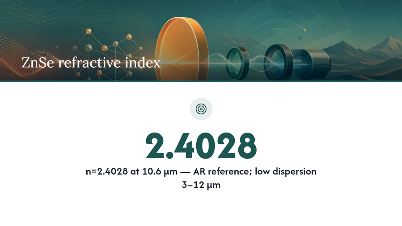
The value n = 2.4028 at 10.6 µm is the most cited figure in CO2-laser optical design and is the basis for AR coating centre-wavelength calculations. Dispersion across the 3–12 µm band is relatively low, which simplifies achromatic design for broadband IR systems but still requires careful Sellmeier modelling for multi-element lenses. Most optical design tools (Zemax OpticStudio, CODE V) include ZnSe dispersion data; always verify the data version matches your vendor’s measured values before finalising a design.
Focal shift under thermal load is a practical concern. The thermal coefficient of refractive index (dn/dT) for ZnSe at 10.6 µm is approximately 6.1 × 10⁻⁵ per °C, meaning a 10 °C rise in lens temperature shifts the focal point measurably in a tight-focus CO2 system. For a 100 mm focal-length lens, a 20 °C temperature rise produces a focal shift on the order of several hundred micrometres — significant for precision cutting or marking applications. Thermal management of the optic mount is therefore part of the optical design, not an afterthought.
AR coating design for ZnSe must account for the high index contrast at the ZnSe/air interface. A single-layer MgF₂ coating, effective on lower-index substrates, performs poorly on ZnSe; multi-layer designs using materials such as ZnS and ThF₄ (or fluoride alternatives) are standard for 10.6 µm AR coatings. The coating bandwidth must match the system’s operating wavelength range, particularly for broadband thermal imaging applications spanning 8–12 µm.
Absorption, scattering and LIDT: what CO2-laser designers must know
Bulk absorption is the dominant performance-limiting factor for ZnSe in high-power CO2-laser systems. Laser-grade CVD ZnSe is manufactured with tight control on impurity levels and crystal defect density to achieve low absorption coefficients in the 10–11 µm band. Even small increases in bulk absorption — caused by residual impurities, grain boundary defects or subsurface polishing damage — translate directly into localised heating, thermal lensing and, at sufficient power density, catastrophic fracture.

High-power ZnSe optics require documented bulk absorption testing, with CO2 laser vacuum calorimetry being the recommended method for quantifying absorption at the operating wavelength. Calorimetric testing measures the temperature rise of the optic under known incident power, yielding an absorption coefficient in ppm·cm⁻¹ that can be compared against a specified acceptance limit. Requesting this test result as part of the material certificate is standard practice for optics used above a few hundred watts.
Scattering losses arise from bulk inclusions, grain boundaries in CVD material, and residual surface roughness after polishing. Their effect is twofold: they reduce transmitted beam quality (important for tight-focus applications) and create localised absorption hot spots that initiate damage at power densities well below the bulk LIDT. A surface microroughness specification of Ra ≤ 1 nm is typical for laser-grade ZnSe; coarser surfaces scatter disproportionately at 10.6 µm.
LIDT guidance for CO2 systems:
- Request LIDT test results that match your actual operating conditions: pulse duration, repetition rate, spot size and beam profile must mirror the real system.
- Continuous-wave LIDT figures are not directly applicable to pulsed systems; the relevant parameter for pulsed CO2 is peak fluence (J/cm²) at the operating pulse duration.
- SPIE proceedings document experimental LIDT characterisation methods for ZnSe and related IR materials; referencing these when writing acceptance criteria gives your specification a defensible technical basis.
- Coating LIDT is typically lower than substrate LIDT; always request coating-inclusive damage threshold data, not bare-substrate figures.
- Specify the test method (ISO 21254 series or equivalent) on the purchase order to avoid ambiguity.
Practical mitigation steps:
- Choose the minimum thickness consistent with structural requirements — thinner optics accumulate less bulk absorption per pass.
- Specify heat-sinking or active cooling for optics in continuous-wave systems above 100 W.
- Require polishing to laser-grade surface finish and confirm with surface roughness measurement data in the acceptance documentation.
Pro Tip: Request the calorimetric absorption test report for the actual batch, not a generic grade specification. Absorption can vary between production runs even within the same material grade.
Thermal, mechanical and chemical limits of ZnSe optics
ZnSe is a relatively soft, brittle material with a density of approximately 5.27 g/cm³. Its mechanical properties set firm limits on mounting design and handling procedures that engineers must respect from the outset.
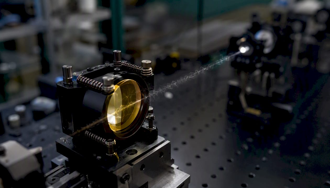
The thermal expansion coefficient of ZnSe is approximately 7.1 × 10⁻⁶ per °C, which is moderate but not negligible in precision mounts. Differential thermal expansion between a ZnSe optic and a metal mount (aluminium at ~23 × 10⁻⁶ per °C, for example) generates stress at the contact points under thermal cycling. This stress can induce birefringence in the optic and, in severe cases, edge cracking. Compliant mounting — using elastomeric retaining rings or spring-loaded cells rather than rigid clamping — is the standard engineering response.
The dn/dT value of approximately 6.1 × 10⁻⁵ per °C at 10.6 µm is positive, meaning the refractive index rises with temperature. In a CO2-laser lens, this produces a thermally induced positive lens effect (thermal lensing) that shifts the focal point towards the lens as the optic heats up. For systems with tight depth-of-focus requirements, this shift must be modelled and either compensated mechanically or managed by controlling the optic’s steady-state temperature.
ZnSe has a Knoop hardness of approximately 120 kg/mm², placing it in the soft-to-medium range for optical materials. It scratches readily and is susceptible to edge chipping during handling. Fracture toughness is low, making impact resistance poor; a dropped ZnSe lens is likely to chip or fracture. These properties make handling protocols and protective packaging critical throughout the supply chain.
Chemically, ZnSe is non-hygroscopic and stable under normal laboratory and industrial conditions. It does not dissolve in water and is resistant to most organic solvents. However, it oxidises at elevated temperatures: sustained exposure above approximately 300 °C in air leads to surface oxidation, which degrades transmission and coating adhesion. Acid cleaning agents must be avoided entirely, as they attack the ZnSe surface. Humidity and UV exposure have limited effect on bulk ZnSe but can degrade AR coatings over time, particularly oxide-based films that were not optimised for the ZnSe surface chemistry.
How ZnSe is supplied and graded: CVD, surface quality and what to specify
The dominant manufacturing route for optical-grade ZnSe is chemical vapour deposition (CVD), in which zinc vapour reacts with H₂Se at elevated temperature to deposit polycrystalline ZnSe on a mandrel. CVD ZnSe offers good uniformity of composition and low impurity levels across large boules, making it the preferred form for laser-grade optics. ZnSe is the inorganic compound with a II–VI semiconductor structure that lends itself well to CVD growth, producing material with consistent optical properties across production batches.
Single-crystal ZnSe, grown by physical vapour transport or Bridgman methods, offers lower scattering in some wavelength regions but is more expensive, harder to obtain in large sizes, and less commonly specified for standard CO2-laser optics. For most industrial laser applications, CVD ZnSe is the correct choice.
Surface and dimensional specifications to include on every purchase order:
- Surface figure: λ/10 or better (at 10.6 µm) for lenses; λ/4 for windows in lower-coherence systems. State the test wavelength explicitly.
- Surface quality (scratch-dig): 20-10 for laser-grade optics; 40-20 is acceptable for windows in lower-power or non-imaging applications.
- Surface roughness: Ra ≤ 1 nm for laser-grade polished surfaces; confirm with profilometer or white-light interferometry data.
- Centring and wedge: specify wedge angle (typically ≤ 1 arcminute for windows, ≤ 30 arcseconds for lenses) to control ghost reflections and beam deviation.
- Diameter and thickness tolerances: ±0.1 mm on diameter and ±0.05 mm on thickness are achievable with precision CNC grinding; tighter tolerances are possible but increase lead time and cost.
- Clear aperture: state the minimum clear aperture as a percentage of the total diameter (typically 90%).
- Coating specification: AR coating design wavelength, reflectance target per surface, and acceptance test method.
Common defects to inspect for on incoming goods include subsurface polishing damage (detectable by phase-contrast microscopy), bulk inclusions visible under transmitted illumination, edge chips, and coating delamination at the periphery. A brief incoming inspection protocol — visual examination under oblique illumination, spot-check transmission measurement at 10.6 µm, and surface roughness verification — catches the majority of these defects before system integration. For guidance on component design tolerances and inspection steps, a structured approach to specifying acceptance criteria reduces rework significantly.
Where ZnSe is used and the design rules that matter
ZnSe’s combination of broad IR transmission, low bulk absorption and reasonable mechanical workability makes it the standard material for several distinct application classes.
CO2-laser optics are the primary market: focusing lenses, collimating lenses, output windows and beam-combiner substrates for laser cutting, welding, marking and medical laser systems all commonly use ZnSe. The material’s performance at 10.6 µm is well characterised, and the supply chain for laser-grade CVD ZnSe is mature. For a broader perspective on engineered glass types used in high-precision laser and optical systems, ZnSe sits in a distinct performance class from oxide glasses.
Thermal imaging windows use ZnSe where broadband 8–12 µm transmission is required with good mechanical durability. ZnSe is preferred over germanium in applications where some visible transmission is useful for alignment, and over chalcogenide glasses where dimensional stability under temperature cycling is critical.
Spectroscopic optics and ATR prisms exploit ZnSe’s transmission across the mid-IR fingerprint region (4–12 µm), making it a standard substrate for attenuated total reflectance (ATR) accessories in FTIR spectrometers.
Practical design rules:
- Thickness vs transmittance: thinner is better for transmittance, but structural requirements and pressure-window applications set a lower limit. Model the transmittance at your required thickness before finalising the specification.
- Wedge: a small wedge (1–3 arcminutes) on windows eliminates back-reflection interference fringes in coherent systems without measurably deflecting the beam.
- Mounting: always use compliant mounts. Never clamp ZnSe rigidly between metal surfaces. Spring-loaded or elastomeric retaining rings are standard.
- AR coating bandwidth: match the coating design wavelength to your system’s actual operating wavelength. A coating optimised for 10.6 µm performs poorly at 9.3 µm (another common CO2 line) and vice versa.
When ZnSe is not the right choice: for applications requiring higher hardness and scratch resistance, materials such as sapphire or spinel are more appropriate. For long-wave IR beyond 20 µm, materials with wider transmission bands are needed. For applications where cost dominates and transmission at 10.6 µm is secondary, lower-grade IR materials may suffice.
How to specify ZnSe optics and source them in the UK
Specifying ZnSe optics correctly at the purchase-order stage is the single most effective way to avoid costly rework or system downtime. The following checklist reflects standard procurement practice for laser-grade ZnSe in UK industrial and defence applications.
Purchase order checklist:
- Material grade: laser-grade CVD ZnSe with stated absorption specification (ppm·cm⁻¹ at 10.6 µm)
- Thickness and diameter with stated tolerances
- Surface figure (test wavelength stated), surface quality (scratch-dig), and surface roughness (Ra, measurement method)
- Wedge angle specification
- AR coating: design wavelength, reflectance target per surface, coating material system, and batch adhesion test certificate
- LIDT test report: test method (ISO 21254 or equivalent), pulse duration, spot size, and pass/fail threshold
- Transmission curve: measured on the actual batch, normalised to the specified thickness
- n(λ) table or Sellmeier coefficients for the batch (if required for design verification)
- Batch traceability: material certificate, production batch number, and inspection records
Test documents to request from your supplier:
- Measured transmission curve with sample thickness stated and spectrophotometer settings noted
- Calorimetric bulk absorption test report for the batch
- Coating adhesion test certificate (tape test, thermal cycling, or equivalent per MIL-C-48497 or ISO 9211)
- Surface roughness measurement data (profilometer trace or white-light interferometry report)
- LIDT test report with full test conditions
Pro Tip: Always request the transmission curve for the actual production batch, not a generic grade curve. Batch-to-batch variation in CVD ZnSe is real, and a curve measured on a different lot tells you nothing about the optic you will receive.
UK sourcing practicalities: lead times for custom ZnSe optics from UK-based suppliers typically run 4–8 weeks for standard sizes; bespoke dimensions or tight tolerances extend this. Optics sourced from outside the UK may require commodity code classification under the UK Global Tariff (HS code 9001.90 for optical elements), and import documentation must accompany the shipment. Packaging for transport must protect edges: foam-lined individual containers with edge protection are standard, and optics should never be stacked face-to-face without interleaving tissue.
Precision Glasses supplies certified, batch-traceable ZnSe optics with full documentation support, including transmission curves, coating adhesion certificates and LIDT test reports on request. Their quality processes include batch-level traceability and inspection records aligned with the procurement checklist above.
Safety, handling and environmental considerations for ZnSe optics
ZnSe contains selenium, which is toxic at elevated concentrations. Bulk ZnSe in its solid, polished form presents minimal risk under normal handling, but grinding, polishing and machining operations generate fine particulate that must be controlled. In a laboratory or factory environment, the following practices apply.
Safe handling:
- Wear nitrile or latex gloves when handling polished ZnSe optics; skin oils accelerate surface contamination and can degrade AR coatings.
- Use lens tissue or optical-grade foam for contact; never place a polished surface on an unprotected bench.
- Handle optics by the edges only; avoid contact with the clear aperture.
- Use padded tweezers or vacuum pickup tools for small optics.
Toxicity and disposal:
- Solid ZnSe optics are classified as non-hazardous for transport under normal conditions, but waste material from machining or damaged optics should be treated as potentially hazardous due to selenium content.
- In the UK, selenium-containing waste is subject to the Hazardous Waste Regulations 2005 (England and Wales) and equivalent Scottish and Northern Irish legislation. Dispose of ZnSe waste through a licensed hazardous waste contractor.
- Do not dispose of ZnSe waste via general industrial waste streams.
Cleaning and maintenance:
- Clean ZnSe optics with optical-grade isopropanol (IPA) or acetone applied with lens tissue using a drag-wipe technique; never rub.
- Avoid acidic cleaning agents entirely; they attack the ZnSe surface and will destroy AR coatings.
- For AR-coated surfaces, minimise cleaning frequency; each cleaning cycle carries a risk of mechanical damage to the coating.
- Store optics in sealed, dry containers away from UV sources. Prolonged UV exposure can degrade some AR coating materials, particularly fluoride-based films.
- Long-term storage in desiccated conditions is recommended to protect coating integrity.
What experience with ZnSe optics actually teaches you
The specification documents for ZnSe are thorough, but the failure modes that cause real project delays rarely appear in datasheets. Two issues come up repeatedly in practice.
The first is AR coating delamination. Oxide-based thin films adhere poorly to ZnSe’s surface chemistry, and coatings that pass a room-temperature tape test can still delaminate under the thermal cycling of a CO2-laser system. The mitigation is straightforward but frequently skipped: insist on vacuum-deposited coatings validated specifically for ZnSe substrates, with batch-level adhesion certificates that include thermal cycling data. A supplier who cannot provide this documentation is telling you something important about their process control.
The second is thickness normalisation on transmission curves. Engineers regularly compare vendor curves without correcting for sample thickness, then discover after delivery that the optic transmits less than expected at their operating wavelength. The fix is simple: ask the vendor to state the sample thickness on the curve and apply Beer-Lambert correction before comparing. This takes five minutes and eliminates a common source of specification disputes.
A short incoming inspection protocol — visual check under oblique illumination, a spot transmission measurement at 10.6 µm, and a surface roughness check — catches most fatal defects before the optic reaches the system. The cost of this inspection is trivial compared to the cost of a field failure.
Precision Glasses: certified ZnSe optics with full documentation
Precision Glasses manufactures and supplies custom optical components for demanding industrial and defence applications, including ZnSe optics specified to laser-grade standards. Where many suppliers offer standard catalogue items with generic grade documentation, Precision Glasses provides batch-traceable material certificates, measured transmission curves for the actual production batch, and coating adhesion certificates as standard deliverables.

For CO2-laser and IR imaging applications, Precision Glasses can supply ZnSe windows, lenses and custom-form optics with AR coatings validated for ZnSe substrates, LIDT test reports on request, and full surface quality documentation. The team works directly with engineering and procurement teams to align specifications with system requirements before manufacture begins, reducing the risk of costly rework.
To request a quote or discuss your ZnSe optic specification, contact Precision Glasses via the technical glass enquiry page.
Sources
The following references provide primary data and peer-reviewed findings for ZnSe optical properties, LIDT characterisation and coating performance.
- Zinc Selenide Laser Grade (Lakeshore) — transmission and n(λ) datasheet
- Optical materials datasheet (Coherent) — ZnSe properties and QA notes
When requesting documentation from vendors, ask specifically for the raw test data files (not just summary certificates), the spectrophotometer settings used for transmission curves, and the thermal cycling protocol used for coating adhesion tests. These details allow independent verification and support any future specification dispute.


