

Yes. Glass is routinely slot machined to optical and functional tolerances, and for most jobs the right starting method is diamond micro-milling or abrasive-assisted micro-milling. Success hinges on staying within the ductile-mode chip thickness, so cracks don’t propagate below the surface. Get the feed, depth of cut, fixturing and coolant right, and glass behaves far more predictably under a CNC spindle than most engineers expect.
TL;DR:
- Diamond micro-milling offers the highest precision and repeatability for slots from a fraction of a millimeter up to several millimeters, making it suitable for tight tolerances.
- Maintaining chip thickness below a critical threshold is essential to stay in ductile mode, preventing surface microcracks that impair optical quality and performance.
- High spindle speeds with low feed rates are recommended for controlling surface roughness and achieving optimal slot quality during CNC glass machining.
- Proper fixture setup with vacuum tables and stress-relief radii at slot terminations reduces risk of cracking and chatter, especially for thin or fragile glass panels.
- Manufacturers like Precision Glasses provide batch traceability, optical transmission testing, and pre-developed process data to ensure high-quality, precision glass slots without extensive in-house development.
Table of Contents
- Which glass slot machining methods actually work?
- What tooling and machine specifications does glass slot machining need?
- How do feed, speed and depth of cut control the ductile–brittle transition?
- What coolant and abrasive media suit precision glass slots?
- How do you fixture thin glass without inducing breakage?
- How do you measure roughness, transparency and slot tolerances?
- What design choices make a glass slot easier to machine?
- What causes chipping, smearing or cracking, and how do you fix it?
- How do you run a first trial slot machining pass on an optical panel?
- How does Precision Glasses approach precision slot machining?
- What should engineers prioritise in their first slot machining trial?
- Where can engineers get glass slots machined to precision tolerances?
- Where can you read more on glass slot machining?
- Sources
Which glass slot machining methods actually work?
Four techniques dominate real production floors, and each suits a different combination of slot size, edge quality and batch volume.
Diamond micro-milling uses diamond-coated or diamond-plated endmills on a rigid CNC platform. It offers the tightest dimensional control and the best repeatability for slots from a fraction of a millimetre up to several millimetres wide, and it’s the default choice when a drawing specifies a tolerance band rather than “close enough.” The trade-off is tool wear and the need for careful parameter control to avoid brittle fracture.
Ultrasonic-assisted machining superimposes high-frequency vibration on the tool, which reduces cutting forces and helps with harder, thicker sections. It’s particularly effective on borosilicate and some ceramic-glass composites, though the equipment investment is higher and cycle times run slower.
Abrasive slurry cutting and lapping-style slotting work well for softer geometries and larger clearance slots where optical finish is secondary to throughput. It’s cheap and forgiving but struggles to hold tight positional tolerances.
Laser machining (typically picosecond or femtosecond) suits very fine slots or micro-features where thermal damage must be minimised, but it comes with lower material removal rates and higher per-part cost for anything beyond micro-scale features.
- Diamond micro-milling: best all-round accuracy and finish, moderate cost
- Ultrasonic-assisted: best for thicker or harder sections, higher equipment cost
- Abrasive slurry: highest throughput, weakest tolerance control
- Laser: best for micro-features, slowest for larger slots
Surface quality and throughput sit at opposite ends of a see-saw here. Choosing the method means deciding first which end of that see-saw the application actually needs.
What tooling and machine specifications does glass slot machining need?
Cutter geometry and machine rigidity matter more in glass than in most metals, because glass has almost no plastic deformation to absorb a poorly chosen parameter.
Diamond burrs and diamond-coated endmills, typically resin-bond or electroplated diamond grit, are the standard cutting tools for CNC glass work, and industry application notes confirm diamond tooling and high-speed cutting as the accepted route for producing slots, bevels and other optical features. Cutter diameter should be chosen against the slot’s minimum internal radius, since you cannot cut a corner tighter than the tool that made it.
- Cutter type: electroplated or resin-bond diamond endmills, sized to the slot’s minimum radius
- Spindle speed: high RPM, commonly high spindle speeds for micro-slots, to keep chip load low at practical feed rates
- Runout: as close to zero as the spindle and toolholder allow. Excess runout turns a single-edge cut into an uneven multi-edge chatter event
- Machine stiffness: a rigid gantry or bridge structure minimises deflection under even light glass-cutting loads
- Toolholding: shrink-fit or high-precision collet systems outperform standard collets for holding concentricity at small diameters
Shop-floor guidance on cutting glass with CNC equipment consistently favours high spindle speeds paired with low feed rates, and that combination remains the safest default before you start tuning for a specific part.
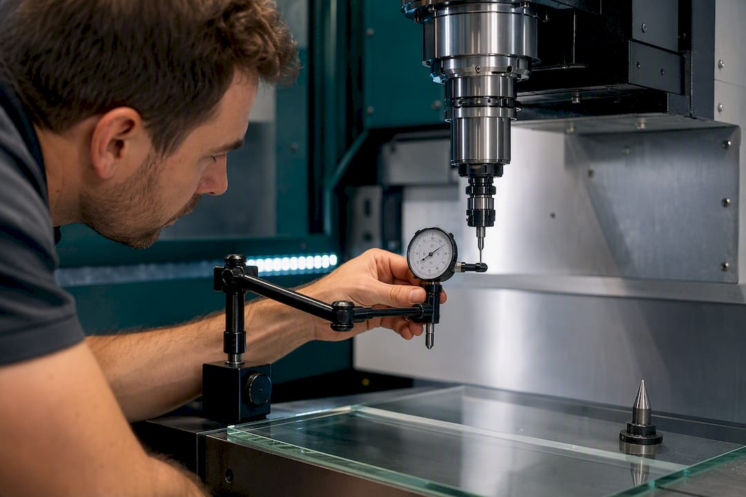
Pro Tip: Check spindle runout with a dial indicator before your first trial cut, not after a cracked part tells you something was wrong. Anything above a few microns at the tool tip is worth chasing down before you touch glass.
How do feed, speed and depth of cut control the ductile–brittle transition?
Glass doesn’t machine like metal because it has no yield point to speak of. It’s ceramic in character, so cutting it well means keeping the process in what researchers call ductile mode rather than brittle mode. In ductile mode, the material shears and flows on a microscopic scale rather than fracturing, and that’s what produces a smooth, transparent edge instead of a chipped, milky one.
The controlling variable is the undeformed chip thickness, the theoretical thickness of material each cutting edge removes per pass. Keep that thickness below a critical value and the cut stays ductile. Push past it and the glass fractures ahead of the tool, leaving subsurface microcracks that no amount of polishing fully removes. Peer-reviewed work on micro slot milling of glass quantifies exactly this relationship, tying acceptable feed per tooth and cutting depth directly to the ductile–brittle threshold.
Practical steps for developing your own parameters:
- Start conservative: low feed per tooth (often a few microns) and shallow depth of cut, well below what the tool’s rated capacity suggests.
- Cut a short trial slot and inspect the edge under magnification for chipping or a frosted, brittle-mode appearance.
- If the edge looks clean, increase feed per tooth in small increments until you find where brittle fracture begins.
- Back off a modest safety margin from that threshold to build in a safety margin for tool wear and material variation.
- Re-verify after tool wear reaches a meaningful fraction of its expected life, since a dulling edge raises the effective chip thickness at a given feed.
Statistic Callout: The same micro slot milling study found a measurable, quantifiable correlation between surface roughness and optical transparency, meaning the finish you can measure with a stylus predicts, with reasonable confidence, how the slot will perform optically.
Single-pass slot milling can be genuinely productive once parameters are locked in, but multi-pass upmilling tends to give better edge quality and less tool deflection on demanding jobs, at the cost of cycle time. Where a slot feeds directly into an optical path, that trade generally favours the extra pass.
What coolant and abrasive media suit precision glass slots?
The right fluid or media choice depends entirely on whether the slot needs to stay optically clear or simply needs to be dimensionally correct.
Water-based coolants are the workhorse for most diamond milling operations. They carry heat and chips away efficiently and are compatible with almost every glass composition used in industrial and optical parts. Oil-based coolants appear less often in glass work but can help in specific ultrasonic-assisted setups where lubricity matters more than heat removal. Abrasive slurries, usually a fine grit suspended in a carrier fluid, suit lapping-style slotting rather than milling, and they demand tighter contamination control because spent grit and glass swarf both need continuous filtration.
- Water-based coolant: standard choice for diamond milling, good heat removal, low contamination risk
- Oil-based coolant: niche use in ultrasonic-assisted processes
- Abrasive slurry: suited to lapping and slower slotting, needs active filtration
- Air blast/dry cutting: preferred where any liquid residue would compromise a downstream coating or bonding step
Filtration matters more than most engineers assume. Application guidance from optics manufacturers stresses that particle and contamination control during coolant or slurry use directly protects the surface quality that later determines optical transmission. A contaminated coolant loop can undo weeks of parameter tuning in a single production run.
How do you fixture thin glass without inducing breakage?
Glass has almost no tolerance for point loading or uneven clamping. A fixture that would be perfectly fine for aluminium can crack a thin glass panel simply by concentrating stress at one corner.
Vacuum tables spread the holding force across the full part surface and are the default choice for flat panels and thin sheets, since they avoid the localised pressure that mechanical clamps create. Sacrificial support layers, often a compliant material bonded or vacuum-held beneath the workpiece, help where a slot must cut close to an edge or where the panel would otherwise flex under cutting forces. Mechanical clamps still have a place for thicker or irregular parts, but placement matters: clamp near the part’s structural mass, never near a feature that’s about to be cut away.
- Vacuum chucking: best default for flat, thin panels
- Sacrificial backing: prevents breakout and flex near edges and through-cuts
- Mechanical clamps: reserve for thicker parts, positioned away from cut features
- Runout and vibration checks: verify before every new fixture setup, not just after a new tool change
Pro Tip: If chatter marks appear on an otherwise well-parameterised cut, check the fixture before touching the feeds and speeds. In many shops, clamping stress and vibration cause more scrap on thin glass than tool wear ever does.
How do you measure roughness, transparency and slot tolerances?
Acceptance criteria for a machined glass slot should cover three things: dimensional accuracy, surface roughness, and, where relevant, optical transmission.
Contact and non-contact profilometry give you a direct Ra (average roughness) figure, and it’s the single most useful number for predicting optical behaviour. The Precision Engineering study on micro-slot milling demonstrated a measurable correlation between surface roughness and transparency, which means a roughness spec can substitute, in practice, for a full transmission test during in-process checks. Full transmission measurement with a spectrophotometer remains the final word when the part is destined for an optical path, since roughness alone doesn’t capture every source of scatter.
- Contact/non-contact profilometry: primary tool for Ra measurement during process development
- Optical microscopy: quick check for chipping, smearing or brittle-mode fracture at the edge
- Spectrophotometry: definitive transmission check for optically critical parts
- CMM or vision metrology: dimensional verification of slot width, depth and position
For tolerancing, treat slot width and depth tolerances the way you would for a hardened tool steel part rather than a soft metal. Glass holds dimension well once cut, so tight tolerances are achievable, but the tolerance on edge condition (chip-free length, radius) often needs its own callout separate from the dimensional tolerance.
What design choices make a glass slot easier to machine?
Design decisions made before the drawing ever reaches a machinist determine most of the scrap rate. A few rules consistently separate an easy job from a troublesome one.
Avoid sharp internal corners smaller than the smallest practical cutter radius; specify a minimum internal radius rather than leaving it to the machinist to interpret. Add a chamfer or radius to every slot’s top edge, since an unbroken sharp edge is the single most common chip-out point during cutting and handling. Where a slot passes right through the part, design in a sacrificial break-out zone or plan the toolpath to exit into scrap material rather than finished edge, which avoids the blowout that happens when a tool exits an unsupported thickness.
- Specify minimum internal radii explicitly, tied to realistic cutter sizes
- Call out chamfers on all top edges of through-slots and blind slots alike
- Add stress-relief radii at slot terminations rather than square stops
- State material family (fused silica, borosilicate, aluminosilicate) on the drawing, since each carries different achievable aspect ratios and finishing routes, as precision glass processing guidance outlines
Fused silica tends to machine cleanly at fine feeds but is comparatively expensive; borosilicate and aluminosilicate offer more forgiving cost profiles with somewhat different achievable slot depth-to-width ratios. A step-by-step design guide is worth reviewing before finalising drawing callouts.
What causes chipping, smearing or cracking, and how do you fix it?
Most defects trace back to one of three causes: excessive chip thickness, poor fixturing, or a dull tool. Matching the symptom to the likely cause saves hours of trial-and-error.
- Edge chipping along the slot usually means the chip thickness exceeded the ductile-mode threshold. Reduce feed per tooth first, then depth of cut if chipping persists.
- Smearing or a glazed, discoloured finish points to heat buildup, often from insufficient coolant flow or a dull tool generating friction instead of cutting. Check coolant delivery before replacing the tool.
- Cracking away from the cut line almost always indicates fixture stress or a clamp positioned too close to the feature. Reposition clamps and check for flatness under vacuum before blaming the parameter set.
- Inconsistent results between parts suggests spindle runout or tool wear creeping up. Recheck runout and rotate in a fresh tool.
If chipping or cracking persists after three parameter adjustments, stop the run rather than burning through material. That’s the point to consult a specialist supplier with process history on the exact glass type.
How do you run a first trial slot machining pass on an optical panel?
A structured first trial saves far more material than it costs in setup time.
- Inspect the raw panel for existing surface defects or inclusions that could seed a crack during cutting.
- Clean the surface thoroughly and check for flatness on the vacuum table before applying hold-down.
- Mount the diamond endmill, confirm runout with a dial indicator, and set a conservative starting feed and depth of cut.
- Cut a short test slot away from the finished part geometry if material allows, and inspect the edge under magnification.
- Adjust feed per tooth incrementally until the edge is consistently clean, then apply that parameter set to the actual slot.
- Run the full slot, checking mid-cut for any change in cutting sound or spindle load that might signal tool wear.
- Clean the finished part, measure roughness and dimensions, and compare against the acceptance criteria before sign-off.
Pro Tip: Keep a written log of every parameter change against edge quality. Glass machining data doesn’t transfer neatly between machines, but your own log becomes the fastest route to repeatable results on the next job.
How does Precision Glasses approach precision slot machining?
Precision Glasses runs CNC glass machining as part of an integrated design, fabrication and inspection flow, rather than treating slot cutting as an isolated job. Diamond tooling, controlled feed development and dedicated metrology stations work together to hold both dimensional tolerance and optical transmission within specification, part after part.
Every batch carries traceability data back to the raw material lot, and finished slots are checked against both surface roughness and transmission criteria before release, particularly for parts destined for coating. That combination of rigorous quality control and an established fabrication process is what lets engineering teams hand over a drawing with confidence that the acceptance criteria will actually be met, not just aimed at.
What should engineers prioritise in their first slot machining trial?
If there’s one lesson worth internalising before your first trial, it’s this: parameter development on glass rewards patience far more than it rewards clever tooling. Most early failures come from engineers borrowing feed rates from metal machining experience and assuming glass will simply behave a little differently. It doesn’t behave a little differently. It behaves according to fracture mechanics, not plasticity, and that changes almost every assumption about how a cut should feel.
The most common early mistake is chasing cycle time before edge quality is proven. Fix the ductile-mode window first, then optimise speed. Where timelines are tight, partnering with a supplier who already holds process data for your exact glass type will get you to a qualified part faster than running the full development curve in-house.
— Alexandra
Where can engineers get glass slots machined to precision tolerances?
If you’ve read this far because you’re weighing up in-house trials against outsourcing, the calculation usually comes down to how much process data you already have for your specific glass composition. Building that data set from scratch, as the sections above show, takes real iteration time and scrap material most project schedules can’t spare.

Precision Glasses runs diamond micro-milling, abrasive-assisted cutting and full optical inspection as a standard part of its precision glass fabrication service, with batch traceability and transmission testing built into the workflow, rather than bolted on afterwards. For teams specifying medical, defense, aerospace or electronics components where tolerance and optical clarity both matter, that means arriving at a qualified part without running the full ductile-mode development curve yourselves. Material options span fused silica through to technical glass families suited to different aspect ratios and cost targets. If you have a drawing with slot dimensions and tolerances in hand, share it with the team via the Precision Glasses enquiry page and request a feasibility review before committing to a production run.
Where can you read more on glass slot machining?
For deeper technical grounding, the Precision Engineering paper on micro slot milling of glass remains the most rigorous published source on ductile–brittle transition control and transparency correlation. Edmund Optics’ CNC glass machining notes cover machine and tooling capability from a manufacturing standpoint, while practical shop-floor guidance on cutting glass with CNC offers pragmatic starting parameters for early trials.


