
Transparent EMI shielding is a conductive layer or laminate, built from architectures such as ITO, metal mesh, silver nanowire or MXene, that attenuates electromagnetic fields while keeping a window optically usable. It belongs wherever a display, sensor or cockpit window must stay clear yet block radio and microwave interference. The core trade-off never disappears: push shielding effectiveness higher and you typically lose visible transmission or gain haze.
TL;DR:
- Achieving higher shielding effectiveness often reduces visible transparency, and a balance must be struck between these competing needs depending on application requirements.
- Different architectures like metal micro-mesh and multilayer TCO/metal/TCO stacks offer varying trade-offs in conductivity, durability, and manufacturability at different sizes and use cases.
- Reliable performance metrics require examining frequency-dependent shielding effectiveness and transmittance spectra, rather than single peak values or isolated data points.
- Embedded and laminated glass mesh shields outperform surface coatings in harsh environments because they resist oxidation, scratching, and delamination over long-term field use.
- Proper mounting and grounding, including continuous low-impedance contact around edges, are critical to prevent RF leaks and actual shielding failures once integrated into systems.
Table of Contents
- How does transparent EMI shielding actually work?
- What metrics actually tell you if a shield works?
- How should transparent EMI shielding be mounted and grounded?
- How durable is transparent EMI shielding in the field?
- What should go in an EMI shielding procurement checklist?
- Why embedded glass laminates often outperform film alone
- Get a quote on custom EMI shielding glass
- Where to read the underlying lab data
- Sources
How does transparent EMI shielding actually work?
A shielding layer stops electromagnetic energy two ways: reflection off a conductive surface and absorption within the material. Which mechanism dominates, and how well it performs, depends on how the conductive pattern relates to the wavelength you’re blocking. A metal mesh with fine line width and tight spacing acts almost like a continuous conductor at radio and microwave frequencies, yet the open apertures between wires let visible light through largely undisturbed.
Several architectures compete for this job, each with a different balance of optics, conductivity and manufacturability:
- Transparent conductive oxides (TCO/ITO): economical, optically clean, but mechanically fragile and prone to yellowing over time.
- Photo-etched metal micro-mesh (copper or aluminium): very low sheet resistance and strong shielding, ideal when mesh can be embedded or laminated rather than left exposed.
- Silver nanowire (AgNW) networks: flexible and lightweight, good for curved or bendable assemblies, though prone to junction resistance drift without a protective matrix.
- MXene and hybrid composites: emerging materials offering tunable conductivity, still maturing for large-area industrial production.
- Multilayer TCO/metal/TCO stacks: balance conductivity and durability, well suited to large-format displays.
- Metamaterial patterns: resonant structures that reach high transmittance with moderate, frequency-selective attenuation.
What metrics actually tell you if a shield works?
Datasheets throw numbers at you. Four of them matter: shielding effectiveness (SE) in decibels, optical transmittance as a percentage, sheet resistance in ohms per square, and haze. SE is frequency-dependent, so a single figure without a stated band is close to meaningless. Ask for the SE curve across the frequencies your application actually faces, not a headline number lifted from the best-case point on the graph.
Sheet resistance and transmittance pull in opposite directions, which is why engineers use a figure of merit (FoM) that combines the two rather than judging either alone. A material with excellent conductivity but poor transmittance may test brilliantly on a network analyser and look terrible in a cockpit display.
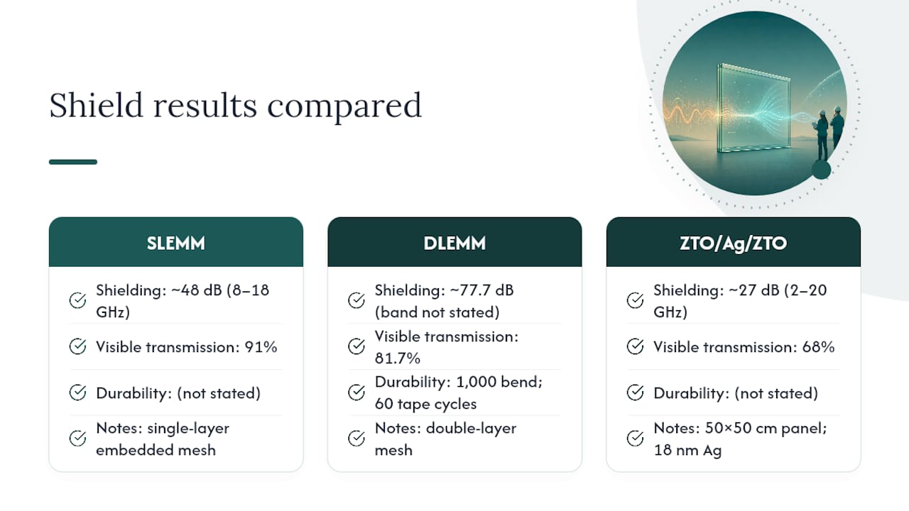
Published lab results give a useful sense of what’s achievable. Single-layer embedded metal mesh (SLEMM) designs have reached roughly 48 dB of shielding across 8 to 18 GHz while holding 91% visible transmission, and double-layer versions (DLEMM) pushed that to around 77.7 dB with 81.7% transmission, remaining stable after 1,000 bending cycles and 60 tape-adhesion cycles. A large-area ZTO/Ag/ZTO multilayer stack on polycarbonate, built with an 18 nm silver layer, delivered roughly 27 dB SE at 68% transmittance across 2 to 20 GHz on a 50 by 50 centimetre panel, demonstrating that multilayer TCO/metal/TCO constructions scale to real display sizes.
Pro Tip: Never accept a single “SE = X dB” claim on a spec sheet. Insist on the full SE-versus-frequency plot and the transmittance spectrum across 400 to 700 nm, so you can compare suppliers on the same axis rather than their preferred cherry-picked point.
How should transparent EMI shielding be mounted and grounded?
Integration decisions matter as much as material choice. A shield that performs perfectly on a test bench can leak badly once it’s mounted, if the edges aren’t grounded properly or the lamination introduces air gaps.
- Adhesive lamination to glass or polycarbonate works for lower-tier applications where cost matters more than optical perfection.
- Clean-room lamination removes bubbles and particulates that would otherwise scatter light and create visible defects under bright ambient conditions.
- Embedded mesh construction, where the conductive layer sits inside the glass rather than on its surface, avoids the machining and cut-to-shape tolerance problems that plague surface coatings.
- Contact edges need continuous, low-impedance grounding around the full perimeter; a single weak ground point creates a slot that leaks RF exactly where you can’t afford it.
- Finishing touches such as blackened borders and anti-reflective (AR) coatings hide the mesh termination and cut glare without touching shielding performance.
Pro Tip: If your assembly has any painted or anodised metal bezel, check the contact resistance between that bezel and the shield’s ground ring before final assembly, not after. Oxide films on aluminium bezels are a common, invisible source of shielding failure in the field.
For engineers working through tolerance stacks and clean-room requirements, it’s worth reviewing how precision fabrication processes handle embedded-layer machining before committing to a design.
How durable is transparent EMI shielding in the field?
Shielding effectiveness measured on day one tells you nothing about year three. The failure modes that actually kill field performance are oxidation of exposed conductive coatings, abrasion from cleaning or handling, delamination at the laminate edges, and thermal cycling that fatigues thin metal traces.
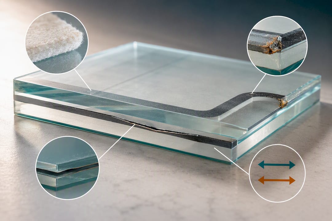
Embedded and laminated mesh constructions outperform surface coatings here because the conductive network sits protected inside the glass, insulated from oxidation and abrasion that would otherwise degrade an exposed ITO or AgNW layer within months in a harsh environment. Flexible AgNW composites bear this out under mechanical stress too: one film retained around 98% and 96% of its original shielding effectiveness after ultrasound and 5,000 bending cycles respectively, evidence that a properly encapsulated network survives repeated flexing.
Before accepting any supplier’s durability claim, request:
- Tape-adhesion test results (industry examples cite 60 cycles as a benchmark).
- Bending-cycle data at the radius your application actually uses, not a generic flat-panel figure.
- Thermal cycling reports covering your expected operating range.
- UV exposure and salt spray results if the unit will see marine or outdoor service.
What should go in an EMI shielding procurement checklist?
A comparable quote starts with a comparable spec. Before you send drawings to any supplier, demand these items back:
- SE versus frequency plot covering your actual operating band, not a single peak value.
- Transmittance spectrum across 400 to 700 nm, plus a stated haze figure.
- Sheet resistance map, since a single-point measurement can hide non-uniformity across a large panel.
- Mechanical tolerances for thickness, flatness and edge finish.
- Coating chemistry and warranty terms, particularly around oxidation resistance.
- Sample size and independent lab verification, so you’re not relying solely on the supplier’s own test bench.
- Custom options available: laminate thickness, CNC machining, AR coatings, blackened borders and realistic lead times.
Cross-reference these against a glass selection process built specifically for electronics-grade specification work, and you’ll catch gaps before they become a failed acceptance test.
Why embedded glass laminates often outperform film alone
Film-based shielding has a place, and flexible AgNW or mesh films genuinely earn their spot in curved or lightweight consumer applications. But once the brief includes defence, aerospace or long-service industrial durability, the conversation changes. Precision Glasses builds embedded, machined and coated glass laminates to engineering tolerances, and that construction choice isn’t cosmetic. A mesh sealed inside glass simply doesn’t oxidise the way an exposed surface coating does, and it doesn’t scratch off during a maintenance cycle.
The honest answer is that off-the-shelf film suits rapid prototyping and low-duty-cycle products well. Bespoke glass lamination earns its cost when the unit has to survive years of thermal cycling, vibration, or repeated handling without a shielding failure showing up as an intermittent fault report months later. Traceability and batch-level documentation matter more in that world than a slightly better transmittance number on a spec sheet.
— Alexandra
Get a quote on custom EMI shielding glass
Precision Glasses builds custom laminated glass with embedded mesh, protective coatings, precision machining and full test documentation, so the shielding performance you specify is the shielding performance you get on the bench and in the field. That’s the practical advantage over generic film suppliers: a construction engineered to your tolerances rather than cut down from a standard roll.

If your project needs a transparent shield that still meets defence or aerospace durability expectations, the technical glass range covers the fabrication options discussed above, from embedded meshes to AR-coated finishes. Precision finishing techniques used in related sectors, such as the edge treatments described by Signature Laser Designs, show how much long-term reliability depends on getting the small details right, not just the headline shielding number. Send drawings, request a sample, or start the conversation with the engineering team directly through the Precision Glasses landing page, and get a quote built around your actual frequency band, transmittance target and environmental spec.
Where to read the underlying lab data
- SLEMM/DLEMM embedded mesh study: source for the 48 dB and 77.7 dB shielding figures and bending/tape durability data.
- ZTO/Ag/ZTO large-area study: the 50 by 50 centimetre multilayer demonstration and sheet resistance figures.
- CA/AgNW/PU flexible film study: durability data under ultrasound and repeated bending.
- Silver mesh shielding review: the case for embedded meshes over exposed coatings in harsh environments.
- Epsilon-mu-near-zero metamaterial study: resonant metamaterial shielding at microwave frequencies.
Engineers specifying against defence or aerospace requirements should read the full methodology sections of each paper, particularly the measurement fixtures used, before comparing figures directly against a supplier’s own test results.
Sources
- Single‐ and Double‐Layer Embedded Metal Meshes for Flexible, Highly Transparent Electromagnetic Interference Shielding | NSF Public Access Repository
- Large-area (50 cm × 50 cm) optically transparent electromagnetic interference (EMI) shielding of ZTO/Ag/ZTO: an analytical/numerical and experimental study
- Transparent and flexible film for shielding electromagnetic interference (ACS Applied Materials & Interfaces, 2018)
- Silver Meshes for Record-Performance Transparent Electromagnetic Interference Shielding (ACS Applied Materials & Interfaces, 2024)
- Ultralow‑metal‑content epsilon‑mu‑near‑zero metamaterials for optically transparent EMI shielding


