
Thermal shock in glass happens when a rapid, uneven temperature change creates tensile stress that exceeds the material’s strength, and the fix begins before the glass ever gets hot: control the maximum temperature difference (ΔT), remove or limit surface flaws, and specify the right glass and heat treatment for the application. Everything else, from material choice to edge finishing testing protocol, exists to protect that one principle.
TL;DR:
- Managing the maximum temperature difference during heating or cooling prevents thermal stress from exceeding glass strength and causing cracks.
- Borosilicate, fused quartz, and glass-ceramics offer higher resistance to thermal shock compared to soda-lime glass, especially for frequent or extreme temperature swings.
- Surface flaws and poor edge finishing significantly increase failure risk; proper grinding, polishing, and controlled heat treatment are essential for durability.
- Testing methods like hot-cold immersion, air-jet cooling, and acoustic emission monitoring help determine a glass’s critical temperature difference and failure threshold.
- Specifying traceable process records and flaw size limits in procurement reduces field failures and ensures thermal-shock resistance is engineered into the design.
Table of Contents
- What is thermal shock in glass?
- How does ΔT and CTE cause glass to crack?
- Which glass materials resist thermal shock best?
- What design and manufacturing steps prevent thermal-shock failure?
- How is thermal shock resistance tested?
- How do you diagnose a thermal-shock failure after it happens?
- How Precision Glasses engineers for thermal-shock resistance
- Balancing schedule, cost and thermal performance
- Specify thermal-shock resistance before it becomes a field problem
- Where to go deeper on thermal shock and glass properties
- Sources
What is thermal shock in glass?
Glass conducts heat poorly. When one face heats or cools faster than the bulk material, the surface tries to expand or contract while the interior lags behind. That mismatch generates tensile stress, and once it exceeds the glass’s tensile strength, a crack starts and runs. This is the mechanism behind thermal shock: a physical fact of how glass moves heat, not a manufacturing defect on its own.
You see the consequence everywhere in industrial glass: a lamp envelope that shatters seconds after switch on, a borosilicate container that survives filling but fails during a cold rinse cycle, an optical window that cracks during rapid environmental cycling in a test chamber. None of these failures need an impact. They need only a temperature gradient the part was not designed to handle.
For manufacturers, this turns thermal shock into more than a design curiosity. It shows up as:
- Field returns and warranty claims tied to unexplained cracking
- Yield loss during annealing, tempering, or coating processes that involve heat
- Safety liability in medical, aerospace, and automotive assemblies where glass failure is not an option
- Costly redesign cycles when a part passes visual inspection but fails in service
Getting the mechanism right early saves far more than it costs to address later.
How does ΔT and CTE cause glass to crack?
Container-industry research groups thermal shock into four practical categories, and the distinction matters because each puts stress in a different place. Type I and Type II thermal shock both place tensile stress on the outer surface, which is why they dominate real-world container and vessel failures. Type III and Type IV involve internal or compressive stress states that are less immediately destructive but still relevant to long-term durability.
- Type I: Rapid cooling of the outer surface (a hot part quenched or rinsed) puts the exterior into tension.
- Type II: Rapid heating of the outer surface produces a similar tensile condition once the surface tries to expand faster than the core.
- Type III and IV: Internal or edge-driven gradients, often from uneven wall thickness or localised contact, that redistribute stress without a uniform external event.
The magnitude of that stress is set almost entirely by two properties: the coefficient of thermal expansion (CTE) and thermal conductivity. A high CTE means a bigger dimensional mismatch per degree of ΔT; low conductivity means that mismatch takes longer to equalise, so the stress lingers. Typical soda-lime float glass carries a thermal conductivity of roughly 0.9 to 1.0 W·m⁻¹·K⁻¹, which is low enough that even moderate ΔT events generate meaningful surface stress.
Statistic worth remembering: experimental and finite-element work on 3mm soda-lime glass found a critical ΔT of around 270°C under aggressive air-jet cooling, with fracture initiating from surface flaws as small as roughly 49 micrometres. That number should reframe how you think about defect tolerance. A flaw invisible to the naked eye is entirely capable of starting a crack once ΔT climbs high enough.
Which glass materials resist thermal shock best?
Material choice sets your thermal-shock margin before a single process step happens; understanding specialized formulations like Bio Glass can guide better chemistry selection for improved thermal performance. CTE differences between glass families are large enough to change which ΔT events a part can survive, and picking the wrong one cannot be fixed downstream with better handling.
- Soda-lime glass: the highest CTE of the common families and the least thermal-shock tolerant; fine for stable environments, risky for rapid cycling.
- Borosilicate glass: a meaningfully lower CTE than soda-lime, which is why it dominates lab glassware and cookware exposed to sudden temperature swings.
- Fused quartz: near-zero thermal expansion over a wide range, giving it the widest safe ΔT window of any common optical glass.
- Glass-ceramics (lithium aluminosilicate, LAS): engineered to push CTE close to zero, and in some formulations negative, making them the choice for extreme or repeated thermal cycling.
Borosilicate improves markedly on soda-lime, but fused quartz and specialised LAS ceramics go further still, particularly where ΔT swings are frequent rather than occasional.
Heat treatment adds a second lever. Tempering induces a compressive surface layer that has to be overcome before tensile failure can begin, which is why tempered glass tolerates substantially larger ΔT than annealed glass of the same composition. Chemical strengthening achieves a similar compressive layer through ion exchange rather than heat, useful where tempering would distort a thin or complex geometry. Annealed glass, by contrast, carries no residual compressive benefit and should be reserved for low-ΔT, low-risk applications.
Where ΔT margins are genuinely tight, the pragmatic move is to specify a low-CTE material or glass-ceramic from the outset rather than lean on strengthening to compensate for the wrong base glass. Our guide to optical properties and thermal expansion covers how CTE interacts with dimensional tolerance in precision optics.
What design and manufacturing steps prevent thermal-shock failure?
Material selection sets the ceiling on thermal-shock resistance. Everything below determines whether a part actually reaches that ceiling in production and in the field.
Edge and surface preparation does more work than most specifications give it credit for. Edges concentrate stress by geometry alone, and a chipped or poorly ground edge adds a flaw on top of that concentration. Fine grinding, polishing, and chamfering reduce both. This matters because even a low-CTE glass still fails at flaws or tensile surface stress concentrations; money spent on surface quality control often reduces risk more per pound than money spent upgrading to a more exotic glass.
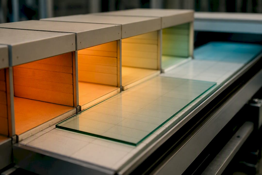
Heat treatment choice should match the service ΔT, not just the budget. Annealing schedules remove internal stress from forming; tempering and chemical strengthening add compressive resistance for parts that will see genuine thermal cycling in service.
Process controls during manufacture carry as much risk as the finished part’s design:
- Preheat mandrels, moulds, and fixtures before contact with hot glass
- Compare heating methods deliberately; infrared gives faster, more localised heating than steam but can create its own gradients if not managed
- Hold correct furnace dwell times so the part reaches thermal equilibrium before the next process step
- Handle warm parts with controlled, gradual temperature transitions rather than ambient-air shock cooling
Assembly-level decisions matter just as much once the glass leaves the furnace. CTE mismatch between glass and its housing, whether metal, ceramic, or polymer, reintroduces the same tensile-stress mechanism at the joint. Flexible mounts, compliant gaskets, and coatings that redistribute load all reduce stress concentration at that interface. For guidance on sealing glass to metal and matching expansion behaviour across dissimilar materials, our design guide covers joint geometry in more depth.
Pro Tip: For many production lines, a controlled preheat ramp reduces thermal-shock risk more reliably than adding a tempering step downstream, because it removes the large ΔT event entirely rather than compensating for it after the fact.
How is thermal shock resistance tested?
Testing exists to find your part’s failure threshold before a customer does. Three methods cover most industrial needs, each revealing a different aspect of behaviour.
- Hot-cold bath immersion: the part is heated to a set temperature, then plunged into a cooling medium at a controlled ΔT; pass/fail is recorded across incrementally larger ΔT steps until failure.
- Air-jet cooling: a more controllable alternative to immersion, allowing precise heat-transfer coefficients and repeatable ΔT ramps, which is how the 270°C critical threshold for 3mm soda-lime glass was established.
- Acoustic emission monitoring: microphones or sensors detect the sound signature of crack initiation, catching damage the moment it starts rather than waiting for visible fracture.
Statistic worth recording in your test log: the same soda-lime study linked crack initiation to flaws on the order of 49 micrometres, which means any inspection standard set above that threshold will miss the population of defects actually causing failures.
Every test result needs four parameters recorded alongside it to be useful later: ΔT achieved, sample thickness, the heat-transfer coefficient of the cooling medium, and dwell time at each temperature extreme. Skip any one of these and the result cannot be reproduced or compared against a different batch.
For standards references, ISO and ASTM both publish thermal expansion measurement and testing procedures worth citing directly in a validation plan; the ISO standards catalogue is a reasonable starting point for locating the specific method your application calls for. A sensible acceptance criterion builds in a safety margin below the measured critical ΔT, typically by testing at the worst-case service condition and requiring a documented margin above it rather than testing exactly at spec. Our quality standards guide covers how this fits into a broader QA programme.
How do you diagnose a thermal-shock failure after it happens?
A cracked part tells you what happened if you read the fracture surface correctly. Thermal-shock cracks typically originate at an edge or surface flaw and propagate in a pattern distinct from impact damage, which tends to show a clear point of contact and radial cracking from that single origin.
- Start with fractography. Look for the origin point; thermal-shock cracks usually start at edges, chips, or scratches rather than mid-face, and the crack front often shows a mirror-mist-hackle pattern radiating from a surface flaw rather than a point impact.
- Bring in non-destructive testing where the failure population is large enough to justify it. Acoustic emission monitoring during a repeat thermal cycle can catch crack initiation before visible fracture, shortening the iterative diagnosis cycle considerably.
- Run FEA once you have a working failure hypothesis. Correlating modelled stress fields against the observed crack location confirms whether the failure matches a thermal-shock signature or points to a different root cause, such as impact or residual stress from a prior process step.
- Estimate the critical flaw size that would explain the failure, then check it against your inspection tolerance. If your surface finishing standard permits flaws larger than that estimate, the fix is in the finishing spec, not the material.
How Precision Glasses engineers for thermal-shock resistance
Precision Glasses builds thermal-shock resistance into its process controls rather than treating it as an afterthought. Precision edge finishing, controlled annealing schedules, and chemically strengthened glass options are standard capabilities across our technical glass range, with batch-level traceability documenting every heat-treatment run.
Engineers writing procurement specifications can request language such as: “surface flaws not to exceed 50 micrometres,” “documented critical ΔT margin above worst-case service condition,” or “traceable annealing/tempering batch records supplied with delivery.” Precise language like this shifts thermal-shock risk from the field back into the design review, where it belongs.
Balancing schedule, cost and thermal performance
The industry default is to reach for tempering whenever a thermal-shock complaint surfaces, and that instinct is often wrong. Tempering fixes a stress problem; it does nothing for a flaw problem, and a fair share of “random” field cracking traces back to surface defects a stronger heat treatment simply masked for longer.
Before switching material, ask whether edge finishing and flaw inspection have actually been tightened. If they have and the part still fails, the material or treatment genuinely needs to change, and that decision belongs in the design review record, not a verbal agreement. A short sign-off checklist helps: document the measured or estimated critical ΔT, the flaw-size tolerance specified, the heat treatment chosen and why, and the safety margin built into the test plan. That record is what protects you when the same question gets asked again eighteen months later.
— Alexandra
Specify thermal-shock resistance before it becomes a field problem
Precision Glasses manufactures custom glass components with thermal-shock resistance engineered in from the material selection stage through edge finishing, heat treatment, and final testing. Unlike generic off-the-shelf glass suppliers, every batch carries traceable process records covering annealing schedules, strengthening treatments, and surface flaw inspection, so your specification document has real data behind it rather than a manufacturer’s assurance.

Our capabilities cover design support for CTE matching and joint geometry, controlled heat treatment across annealed, tempered, and chemically strengthened glass, and thermal-shock testing with documented critical ΔT margins for medical device, defense, aerospace, and electronics applications. If you are specifying a component for a demanding thermal environment, request a technical glass specification sheet or quotation and get the property data and test certificates you need before committing to a design.
Where to go deeper on thermal shock and glass properties
For engineers building out a design review or test plan, these sources cover the ground this article draws on:
- The thermal shock mechanism overview for the underlying physics and material comparisons across glass families.
- Soda-lime float glass property tables for CTE, conductivity, and specific heat data used in stress calculations.
- The IRSM CAS thermal shock study for empirical critical ΔT and flaw-size data on soda-lime glass.
- American Glass Research’s Type I–IV framework for container-specific thermal shock classification.
- The Procedia Engineering modelling paper for transient thermal-mechanical FEA methodology and acoustic emission correlation.
Sources
- Thermal shock — Wikipedia
- Glass
- Thermal shock resistance of a soda lime glass — IRSM CAS (2013)
- Thermal shock in glass containers — American Glass Research (2018)
- Thermal shock effect on glass thermal stress response and crack propagation — Procedia Engineering (2013)


