

The black panel effect is a display technique in which an instrument window appears as one seamless, uniform black surface when unlit, then reveals icons, graphics or a screen the moment it is powered. It suits instrument clusters, HMIs and medical displays wherever a clean, unbroken face matters more than a visible bezel.
TL;DR:
- Maintaining a light transmission tolerance of around ±3% across the panel’s spectral range is critical for achieving a consistent black appearance.
- Thickness variations beyond a micron can create visible hot spots and uneven sheen, making tight process control essential.
- Material choices like neutral-grey PMMA are ideal for precise, thin covers, while films enable easier assembly on hybrid clusters.
- Ensuring proper registration of mask layers and minimizing internal reflections during manufacturing prevent haloing and color inconsistencies.
- Early collaboration with specialized suppliers can reduce lead times and costs by verifying material, process, and design compatibility before tooling.
Table of Contents
- What produces the black panel effect and where it goes wrong
- Choosing the right material and display technology
- The numbers to put in your RFQ
- Design and process controls that keep the black uniform
- Verifying the effect: lab and in-system testing
- Building the RFQ: a procurement checklist
- What twenty years of glass programmes teach about black panel tradeoffs
- Getting a black panel specification into production
- Sources
- FAQ
What produces the black panel effect and where it goes wrong
Neutral grey tinting in a PMMA or polycarbonate substrate blocks enough visible light to hide an unlit display while still letting a backlit graphic punch through when energised. This is an optical balancing act between wall thickness and colourant loading, not a simple paint job. Get the light transmission (LT) too low and the display struggles to break through; too high, and the “off” state looks patchy grey rather than black.
Most failures trace back to a handful of physical causes:
- Thickness variation across the moulded or formed part, even at the micron level, shifts local LT and creates visible hot spots.
- Resin impurities or inconsistent colour batching produce colour drift between production runs.
- Poor registration of black mask printing layers leaves faint haloing around icon cutouts.
- Air gaps at layer interfaces cause internal reflections that read as uneven sheen under ambient light.
- Off-angle viewing exposes hot spots that were invisible at the design viewing angle.
Tinting alone rarely survives contact with a real production line. Minute thickness variations or resin impurities can defeat the entire effect, which is why the material choice and the process controls around it matter as much as the colour formulation itself.
Choosing the right material and display technology
Four technology families dominate black panel specifications, and each solves a different part of the problem.
- Neutral-grey PMMA, such as PLEXIGLAS® moulding compounds, gives precise, repeatable colouring and suits thin, optically demanding cover lenses where transmission versus wall thickness has to be tuned exactly.
- Polycarbonate light-management films, notably Makrofol® LM, enable lensless, formable appliques that skip a moulded lens altogether and simplify assembly on hybrid clusters.
- VA (Vertical Alignment) LCD technology is the usual choice for fixed segment displays needing a strong black background, because VA delivers higher contrast than TN, HTN or STN modes.
- OLED offers genuinely self-emissive deep black, but the burn-in risk on static graphics rules it out for many instrument cluster applications.
Dark grey cast acrylic filters, such as Solaris™ S194, give procurement teams a concrete, customisable sample point when writing an RFQ around specific thickness and surface treatment options. Films and printed appliques suit hybrid clusters where 3D forming and design freedom outweigh the benefit of a rigid cover lens; moulded cover lenses still win where mechanical robustness or thicker optical sections are non-negotiable.
The numbers to put in your RFQ
Vague colour callouts do not survive first-article inspection. Specify light transmission tolerance, thickness control and any near-infrared requirement as hard numbers, not descriptive language.
Pro Tip: Request a spectral transmission curve across the full visible range, not just a single LT percentage, so you can catch a material that passes the average reading but fails at the wavelength your backlight actually emits.
| Parameter | Typical target | Why it matters |
|---|---|---|
| Light transmission uniformity | ±3% across panel | Standard for high-end automotive black panel applications |
| Thickness variation | Micron-level control | Even small deviations create visible hot spots |
| Gloss/haze | Defined per surface finish | Affects perceived uniformity under ambient light |
| NIR transmission (sensor-integrated panels) | Set per sensor spec, wavelength specified as appropriate | Preserves black appearance while keeping sensors functional |
The ±3% LT window is the figure worth anchoring your whole specification around: it is the tolerance cited for optimal light management in high-end automotive implementations, and it is tight enough that suppliers without dedicated process control routinely miss it. Build your acceptance sampling plan and incoming inspection criteria around this figure before production tooling is committed, and confirm the supplier can hold it across the full part geometry, not just at a single test coupon.
Design and process controls that keep the black uniform
Uniformity is designed in long before it is measured. Nominal wall thickness, draft angles and forming limits all need to respect the material’s LT curve, because a part that is thicker at one edge will read darker there even with perfectly consistent resin.
Black mask printing and lensless printed appliques depend on tight registration control between print layers; a misaligned mask shows as a faint edge glow the moment the display lights up. Poorly managed reflections at layer interfaces cause shut-down colour variation under ambient light, which is why index-matching adhesives and careful bondline management matter as much as the substrate itself.
Key controls worth locking into the design pack:
- Nominal wall thickness and draft angles matched to the material’s transmission curve, not a generic moulding default.
- Registration tolerances for every printed mask layer, checked at first article.
- Index-matching adhesive specification for any bonded stack, with bondline thickness called out.
- Anti-glare and scratch-resistant coating transmission loss quantified, not assumed negligible.
- Handling and cleaning procedures that avoid introducing surface contamination before final assembly.
Precision Glasses treats interface reflections and coating interactions as a design-stage problem rather than a defect to catch later, because retrofitting a coating fix after tooling is far more expensive than specifying it correctly from the outset.
Verifying the effect: lab and in-system testing
A black panel spec is only as good as the test method behind it. Photometer or spectrophotometer mapping across the panel surface is the baseline check, and it needs to produce a documented uniformity map, not a single average reading.
- Record a full spectral transmission curve at nominal thickness, then repeat at the thinnest and thickest points on the part.
- Run a grid LT map at defined measurement apertures, capturing mean LT, minimum, maximum and standard deviation across the surface.
- Check viewing angles that match real installation geometry, including low sun angle and low-light cabin conditions.
- Cycle the part through UV exposure and temperature extremes, then re-measure LT to confirm no drift.
- Sign off against a documented threshold: reject if local deviation exceeds ±3% or any point shows a visible localised LT increase.
A practical benchmark worth building into your test protocol is a 5×5 grid LT map at nominal thickness, with a defined aperture size recorded on the test report alongside mean, min, max and standard deviation. Anything outside that band gets flagged before it reaches assembly, not after a customer complaint.
Building the RFQ: a procurement checklist
A supplier that cannot answer these points in writing is not ready for a black panel programme.
- Material and film reference (grade, supplier, neutral grey box sample number).
- Numeric LT tolerance and the wavelength range it applies across.
- Surface finish, coating type and its documented transmission loss.
- Inspection method, sample size per batch, and first-article LT map requirement.
- Batch traceability records tied to colour lot number.
- Lead time commitments and a formal change control clause for any material substitution.
- Packaging, labelling and defect warranty terms in plain, enforceable language.
Precision Glasses builds glass component specifications around exactly this structure, because a checklist with vague terms like “acceptable colour match” invites disputes at incoming inspection rather than preventing them.
What twenty years of glass programmes teach about black panel tradeoffs
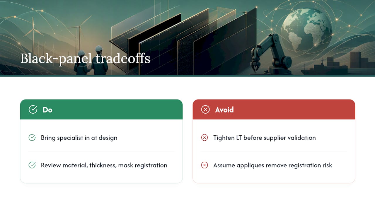
The real tension in every black panel programme is optical quality against cost and lead time. Push the LT tolerance tighter and you narrow the pool of suppliers who can hold it consistently, which extends lead time and raises unit cost. Film-based appliques often cut assembly steps compared with a moulded cover lens, but they shift risk onto registration accuracy during lamination.
None of this is guesswork if you bring a specialist supplier in during the design phase rather than after tooling is cut. The earlier the material, the thickness curve and the mask registration are reviewed together, the fewer surprises show up at first-article inspection.
— Alexandra
Getting a black panel specification into production
A black panel drawing can be turned into a working part faster when the LT tolerance, thickness curve and mask registration are handled under one roof rather than across multiple vendors.

Typical capabilities for such projects cover custom PMMA and polycarbonate components, anti-glare and index-matching coatings, batch-level colour traceability, and a direct path from prototype to production run without re-qualifying a new supplier at each stage. If you have a drawing or a target LT tolerance in hand, the fastest next step is a spec review followed by a small-run prototype before committing to full tooling. Start that conversation by reviewing our precision glass manufacturing workflow and requesting a quote against your specific panel geometry and LT target.
Sources
- Next‑gen black panel displays | Covestro
- Black panel effect: grey coloured PLEXIGLAS® molding compounds — Röhm GmbH
- Solaris™ S194 dark grey filter product page
FAQ
What is the black panel effect on a display?
It is a design technique where an instrument window looks like one solid black surface when off, then reveals lit graphics or a screen when the display is activated.
What light transmission tolerance should I specify?
Aim for light transmission uniformity around ±3% across the panel’s defined wavelength range, verified with a documented LT map.
Is PMMA or polycarbonate better for a black panel cover?
Neutral-grey PMMA suits thin, precisely coloured cover lenses, while polycarbonate films such as Makrofol® LM suit lensless, formable appliques on hybrid clusters.
Why does VA LCD suit black panel segment displays?
VA technology produces a stronger, more uniform black background than TN, HTN or STN modes, which is why it is the common choice for fixed segment instrument displays.
Can black panel cover lenses be supplied to a specific LT tolerance?
Custom PMMA and polycarbonate components can be fabricated to defined light transmission and thickness tolerances, with batch traceability from prototype through to production.


