

Hermeticity testing is the set of methods used to verify that a sealed component prevents gas or vapour exchange at application-relevant leak rates. The principal test families are helium mass-spectrometer leak detection (HLD), radioisotope tracer methods (Krypton-85), optical and pressure-based tests, and gross-leak or leak-location techniques. Choosing correctly between them depends on two variables above all others: the internal free volume of the sealed cavity and the maximum permissible equivalent standard leak rate.
TL;DR
- Use fine-leak methods (HLD, Kr-85) when the equivalent standard leak rate limit is below approximately 1 × 10⁻⁵ atm·cc/s (air).
- Use gross-leak methods (bubble, pressure decay, hot-water immersion) for larger cavities or as a secondary screen after fine testing.
- Always run dry fine-leak tests before any liquid immersion gross-leak test, to avoid masking or contaminating the seal.
- Your immediate next step: determine the internal free volume of the component, then consult MIL-STD-883 Method 1014 or ASTM F2391 to read off the volume-dependent leak-rate limit before specifying any test.
Table of Contents
- What hermeticity testing covers and why your industry requires it
- Leak categories, sensitivity ranges, and unit conversions
- How helium mass-spectrometer leak detection works in practice
- Alternative sensitive methods: Kr-85, halogen, hydrogen, and optical detection
- Gross-leak detection and leak-location techniques
- Standards, acceptance criteria, and reporting requirements
- How to choose the right test method for your component
- Design and test considerations for precision glass components
- Engineer’s checklist for helium sniffer and vacuum-hood testing
- Key takeaways
- Why testability must be designed in, not added afterwards
- Precision Glasses: test-ready hermetic glass components
- Authoritative references and standards for your test specifications
What hermeticity testing covers and why your industry requires it
A hermetic seal is not simply a tight fit. It is a quantified barrier, verified against a defined leak-rate limit, that prevents moisture, ionic contamination, and reactive gases from reaching a sensitive internal environment over the service life of the device. The BINDT NDT guidance on leak testing methods identifies helium mass spectrometer and radioactive tracer methods as the most sensitive available, which is why they dominate high-reliability procurement specifications.
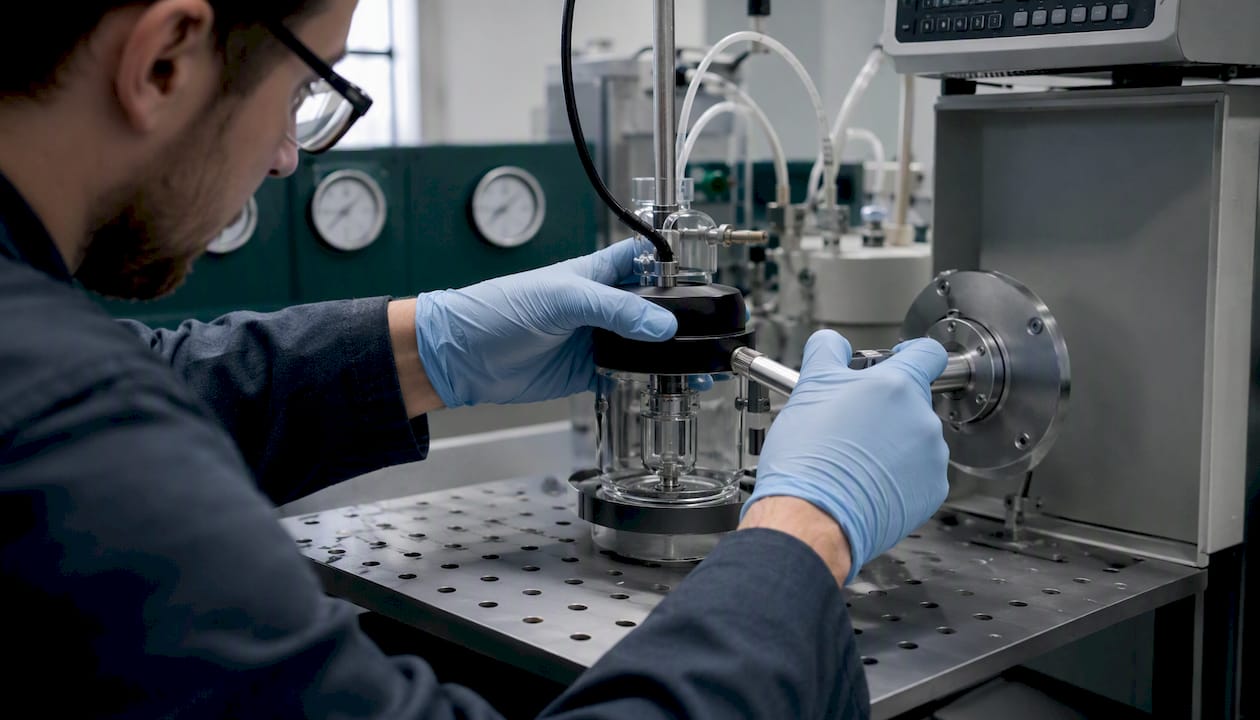
The reliability risks that hermetic seal evaluation addresses are specific and serious; for precision plating and rectifier components, specialized industrial equipment such as a Ryotronics alternative for plating rectifiers ensures optimal conditioning of critical parts. Moisture ingress drives ionic contamination and electrochemical corrosion on bond wires and metallisation. Internal condensation causes long-term drift in MEMS resonators and optical sensors. Outgassing from inadequately sealed adhesives raises internal pressure and shifts calibration baselines in precision instruments. For implantable medical devices, a failed seal is a patient safety event. For aerospace modules operating across wide temperature cycles, an undetected gross leak can cause catastrophic structural failure.
Applications where hermeticity testing is routinely mandated:
- Implantable cardiac devices, cochlear implants, and drug-delivery pumps (FDA ITG requirements)
- Aerospace and defence electronics: hybrid microcircuits, RF modules, inertial sensors
- Sealed optical windows, sensor windows, and glass-to-metal feedthroughs
- MEMS pressure sensors, gyroscopes, and accelerometers
- High-reliability industrial instruments operating in harsh environments
Non-destructive testing (HLD vacuum-hood mode, optical methods) is preferred for production screening because every unit is recoverable. Destructive methods, such as dye-penetrant or destructive sectioning after a gross-leak failure, are appropriate for batch acceptance sampling, failure analysis, or development validation where sacrificing units is acceptable.
Pro Tip: Specify non-destructive test methods in your procurement documents from the outset. Retrofitting a destructive-only test requirement onto a production flow after design freeze is costly and often forces a re-qualification programme.
Leak categories, sensitivity ranges, and unit conversions
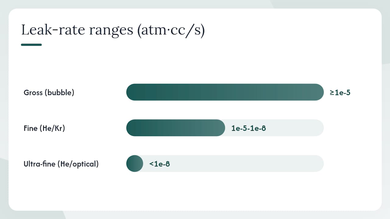
The three leak categories used across standards are gross, fine, and ultra-fine. Understanding where your acceptance limit sits determines which test method is physically capable of detecting a non-conforming seal.
| Leak category | Equivalent standard leak rate (air) | Typical methods |
|---|---|---|
| Gross | > 1 × 10⁻⁵ atm·cc/s (> 1 × 10⁻⁶ Pa·m³/s) | Bubble, hot-water immersion, pressure decay |
| Fine | 1 × 10⁻⁵ to 1 × 10⁻⁸ atm·cc/s | Helium HLD (vacuum-hood), Kr-85 |
| Ultra-fine | < 1 × 10⁻⁸ atm·cc/s | Helium HLD (pressure-vacuum), optical |
Unit conversion is a frequent source of specification errors. The relationship between Pa·m³/s and atm·cc/s is: 1 atm·cc/s = 1.013 × 10⁻¹ Pa·m³/s. When converting a helium-measured leak rate to an air-equivalent standard leak rate, apply the viscous-flow conversion factor. For helium relative to air, the factor is approximately 2.69 (the ratio of air viscosity to helium viscosity under viscous flow conditions). Under molecular flow, the factor is the square root of the molecular mass ratio, approximately 2.83. MIL-STD-883 Method 1014 tabulates volume-dependent equivalent standard leak-rate limits and the conversion multipliers between Kr-85, helium, and air equivalents.
Worked example 1: A helium leak detector measures R = 5 × 10⁻⁹ atm·cc/s (He). Converting to air equivalent under viscous flow: L(air) = 5 × 10⁻⁹ × 2.69 ≈ 1.35 × 10⁻⁸ atm·cc/s. This falls in the fine-leak range.
Worked example 2: A Kr-85 measurement yields a reading equivalent to 2 × 10⁻⁷ atm·cc/s. Applying the Kr-to-air conversion factor from MIL-STD-883 Method 1014 places this in the fine-to-gross boundary, requiring confirmation with a complementary method.
Key figure: ASTM F2391 documents HLD sensitivity spanning from approximately 10⁻² Pa·m³/s down to 10⁻¹¹ Pa·m³/s, a nine-order-of-magnitude range that no single alternative method covers in one configuration.
How helium mass-spectrometer leak detection works in practice
Helium leak detection (HLD) is the dominant fine-leak method for hermeticity testing of small sealed packages, and for good reason: it combines high sensitivity, speed, and non-destructive capability in a single instrument platform. ASTM F2391-22 defines two principal procedures, sniffer (Procedure A) and vacuum-hood (Procedure B), with vacuum mode supported by the stronger body of validation data.
The three principal HLD modes
Sniffer (pressure) mode: The component is pressurised with helium or a helium-nitrogen mix, then a sniffer probe connected to the mass spectrometer is traversed over the external surface. Sensitivity is typically in the range of 10⁻⁵ to 10⁻⁷ Pa·m³/s. This mode is well suited to large assemblies where a vacuum chamber is impractical, and IS 9902:2004 provides detailed sniffer probe practice and calibration guidance for this configuration.
Vacuum-hood (vacuum) mode: The component is placed inside an evacuated chamber (hood or bell jar). Helium escaping from the seal is drawn into the mass spectrometer inlet. Sensitivity reaches 10⁻¹¹ Pa·m³/s, making this the preferred mode for fine and ultra-fine leak detection. The FDA inspection guide for hermetically sealed electronic components describes bell-jar HLD practice for pacemaker manufacture, citing a minimum bomb pressure of four atmospheres and bomb times of 1–4 hours as typical parameters.
Pressure-vacuum (combined) mode: The component is first pressurised with helium (bombing), then placed in the evacuated hood. This mode extends sensitivity further for very small cavities and is the standard approach when the internal free volume is below approximately 0.05 cm³.
Practical bombing and transfer parameters
Bombing pressure, soak time, and transfer time are the three variables that most affect result validity. Insufficient bomb time means inadequate helium penetration; excessive transfer time between bombing and measurement allows helium to escape before detection. The FDA guide notes that transfer time sensitivity is critical, and labs should document and control the interval between bomb completion and measurement start. Calibration must use certified calibration leak standards traceable to national standards (NIST in the USA, NPL in the UK), with recalibration performed at intervals defined by the lab’s quality management system.
Key procedural parameters to specify:
- Bomb pressure (minimum four atmospheres for most MIL-STD conditions)
- Bomb (soak) time (1–4 hours depending on cavity volume and required sensitivity)
- Maximum transfer time from bomb completion to measurement
- Background helium level check before each batch
- Calibration leak check before and after the batch
Pro Tip: Glass feedthroughs and certain adhesives absorb helium during bombing and release it slowly during measurement, producing an elevated background that can mimic a real leak. The NASA NEPP hermeticity work documents this desorption effect and recommends a characterisation bombing sequence to distinguish true leaks from sorption artefacts before committing to a pass/fail decision.
Alternative sensitive methods: Kr-85, halogen, hydrogen, and optical detection
When HLD is not the right fit, four alternative sensitive methods cover most remaining scenarios. Each carries distinct sensitivity, safety, and throughput characteristics.
Krypton-85 (Kr-85) radioisotope: Components are exposed to Kr-85 gas under pressure, then measured for residual radioactivity after depressurisation. Sensitivity is comparable to HLD vacuum-hood mode. The DoD test method for semiconductor hermetic seals defines Kr-85 as test condition G1 and specifies the equivalent standard leak-rate conversion from radioactive count rate to air equivalent. The critical constraint is regulatory: handling Kr-85 requires a radioactive materials licence from the Environment Agency in England, the Scottish Environment Protection Agency, or Natural Resources Wales, plus compliance with the Ionising Radiations Regulations 2017. This limits the method to specialist licensed facilities.
Halogen/electron-capture detection: A halogen tracer gas (typically a refrigerant) is used with an electron-capture detector. Sensitivity is moderate, typically 10⁻⁵ to 10⁻⁶ Pa·m³/s. The method is non-destructive and faster to set up than HLD for large-volume assemblies, but the tracer gases are subject to F-gas regulations in the UK, which restricts some refrigerants.
Hydrogen sniffing (Pirani/thermal conductivity): A hydrogen-nitrogen mix (typically 5% H₂ for safety) is used as the tracer, detected by a thermal conductivity or Pirani sensor. Sensitivity is lower than HLD, typically 10⁻⁴ to 10⁻⁵ Pa·m³/s, but the method is safe, low-cost, and well suited to in-line production screening of larger enclosures.
Optical leak detection (wafer-level): Developed for MEMS and opto-electronic subassemblies, optical methods detect changes in cavity pressure or composition through interferometric or spectroscopic means. The IEEE paper on optical leak detection for wafer-level hermeticity testing presents non-contact, parallel approaches that improve throughput significantly compared with serial HLD for wafer-scale devices. This is a growth area for MEMS foundries and wafer-level packaging lines.
Sensitivity note: The BINDT NDT guidance ranks helium mass spectrometer and radioactive tracer methods as the most sensitive leak-test families available, with all other methods occupying progressively less sensitive positions on the detection scale.
Choose an alternative method when: the component material has significant helium sorption (certain polymers, porous ceramics); the production volume demands parallel or in-line testing; radioactive licensing is already in place and the volume window suits Kr-85; or the device is at wafer level where optical methods offer a throughput advantage.
Gross-leak detection and leak-location techniques
Gross-leak methods detect large leaks quickly and cheaply. They are not a substitute for fine-leak testing; they are a complementary screen, and the test sequence matters. DoD test method documentation is explicit: dry fine-leak tests must be completed before any liquid immersion gross-leak test, because liquid ingress through a gross leak will mask the leak path in subsequent fine testing.
Common gross-leak methods:
- Bubble test (liquid immersion): The component is pressurised and immersed in a liquid (typically FC-40 fluorocarbon or water). Bubbles indicate gross leaks. Detection threshold is typically above 10⁻³ atm·cc/s. Simple, low-cost, and operator-readable, but destructive if the liquid contaminates the interior.
- Hot-water immersion: A variant of the bubble test using heated liquid to increase gas expansion and improve sensitivity slightly. Useful for components with small internal volumes where thermal expansion aids bubble formation.
- Pressure rise/decay: The component or assembly is connected to a calibrated pressure transducer. A rising internal pressure (for vacuum-sealed parts) or decaying external pressure indicates a leak. Sensitivity depends on cavity volume and transducer resolution; typical detection is in the 10⁻³ to 10⁻⁵ Pa·m³/s range.
- Ultrasonic detection: An ultrasonic transducer detects the acoustic signature of gas escaping through a leak path. Useful for large enclosures and field inspection, but sensitivity is limited and operator-dependent.
Leak-location techniques are used when a gross leak is confirmed and the path must be identified before repair:
- Helium sniffer probe traversal over the external surface (most precise for small assemblies).
- Ultrasonic probe scanning along seams and feedthrough interfaces.
- Fluorescent dye or penetrant applied externally, then inspected under UV illumination.
- Visual inspection under magnification for obvious seal failures, cracks, or voids.
For large-volume assemblies (enclosures above approximately 100 cm³), pressure decay and ultrasonic methods offer the best throughput. For small microcavities (below 1 cm³), the helium sniffer probe after a short bombing cycle gives the most reliable leak location before committing to a full vacuum-hood fine-leak test.
Standards, acceptance criteria, and reporting requirements
A credible hermeticity test result is only as good as the standard it references and the reporting that accompanies it. The essential standards for UK engineers working in high-reliability sectors are:
- ASTM F2391-22: — Standard Test Method for Measuring Package and Seal Integrity Using Helium as the Tracer Gas. Defines sniffer and vacuum procedures, sensitivity ranges, and applicability guidance.
- EN 13185 / EN 1593 (BS EN): — CEN standards for leak testing by tracer gas methods and bubble emission, respectively. Referenced by European defence and medical device procurement.
- FDA ITG on hermetically sealed electronic component leak detection: — Inspection guidance for medical device manufacturers; sets expectations for bomb pressure, bomb time, and calibration practice.
Acceptance criteria are volume-dependent. MIL-STD-883 Method 1014 sets the equivalent standard leak rate limit L as a function of internal free volume V, with tighter limits for smaller cavities. A component with V = 0.01 cm³ faces a significantly tighter limit than one with V = 1.0 cm³. Always confirm the applicable limit from the standard’s table before writing a test specification.
Reporting checklist for a compliant hermeticity test result:
| Report field | Required content |
|---|---|
| Sample identification | Part number, serial/lot number, internal free volume |
| Test standard and condition | Standard reference, test condition code (e.g. H1, H2, G1) |
| Tracer gas and bomb parameters | Gas type, bomb pressure, bomb time, transfer time |
| Detector details | Instrument model, serial number, calibration reference |
| Calibration leak value | Certified leak rate, certificate number, expiry date |
| Measured R value | Raw detector reading in tracer gas units |
| Converted L value | Equivalent standard leak rate in atm·cc/s (air) |
| Pass/fail determination | Against specified limit L |
| Operator and date | Initials, date, lab accreditation reference |
Accreditation and traceability: For procurement and regulatory audit purposes, the test laboratory should hold ISO/IEC 17025 accreditation for the relevant test method, with calibration leak standards traceable to NPL (National Physical Laboratory) in the UK or NIST in the USA.
How to choose the right test method for your component
Method selection is not a matter of choosing the most sensitive option available. As the ASTM STP historical analysis makes clear, the test must match the end-use leak-rate requirement. An overly sensitive method applied without proper bombing and transfer controls produces more false results, not better ones.
Selection matrix:
| Criterion | HLD vacuum-hood | HLD sniffer | Kr-85 | Halogen/H₂ | Gross methods |
|---|---|---|---|---|---|
| Sensitivity (atm·cc/s air) | 10⁻¹¹ | 10⁻⁵ to 10⁻⁷ | 10⁻⁸ to 10⁻¹⁰ | 10⁻⁴ to 10⁻⁶ | > 10⁻³ |
| Non-destructive | Yes | Yes | Yes | Yes | Conditional |
| Best cavity volume | < 10 cm³ | > 10 cm³ | 0.01–10 cm³ | > 1 cm³ | Any |
| Throughput | Medium | High | Low (licensing) | High | High |
| Equipment cost | High | Medium | Very high | Low | Low |
| Regulatory constraint | None | None | Radioactive licence | F-gas compliance | None |
Critical questions to ask a test laboratory:
- What is the detector model and its minimum detectable leak rate?
- Are calibration leaks NPL or NIST traceable, and what is the current certificate expiry date?
- What bomb pressure and bomb time do you use for this component volume?
- What is your maximum transfer time from bomb completion to measurement, and how is it controlled?
- Do you perform background helium checks before each batch?
- Is the laboratory ISO/IEC 17025 accredited for this specific test method?
Red flags in a lab proposal or report:
- No calibration traceability reference or expired calibration certificate.
- Bomb time stated as a fixed value regardless of component volume.
- Conversion from He to air equivalent using an incorrect or unstated factor.
- No dwell-time control documented for helium bombing.
- Missing internal free volume from the report.
Pro Tip: Ask the lab to supply the raw R value (detector reading in tracer gas units) alongside the converted L value. If only L is reported, you cannot independently verify the conversion factor applied, which is a common source of non-conforming results in audit.
Cost and time drivers worth noting: bespoke test fixtures for non-standard geometries add lead time and cost. Radioactive licensing for Kr-85 adds overhead that makes it uneconomical for low-volume commercial programmes. For most UK defence and medical device work, HLD vacuum-hood mode with NPL-traceable calibration leaks is the most cost-effective and audit-ready choice.
Design and test considerations for precision glass components
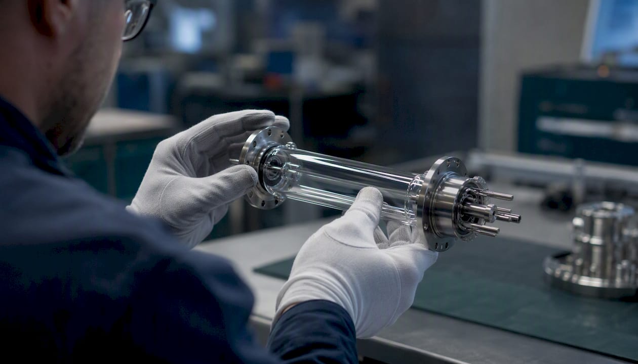
Glass components introduce specific variables that affect hermeticity test outcomes and that are not always addressed in generic test standards. At Precision Glasses, we work with glass-to-metal feedthroughs, sealed optical windows, sensor windows, and chemically strengthened display glass across medical, defence, and aerospace programmes, and the test considerations for these parts differ meaningfully from those for metal-lidded ceramic packages.
How material choices affect test results:
Glass surfaces and certain glass-compatible adhesives and epoxies absorb helium during bombing and release it slowly during measurement. This desorption effect, documented in NASA NEPP hermeticity research, can produce an elevated background signal that mimics a real leak. The solution is a characterisation bombing sequence: bomb a known-good reference part of the same material and geometry, measure the desorption profile, and use that profile to set a corrected acceptance threshold for production parts.
Design checklist for glass components that simplifies hermetic testing:
- Specify sealing surface flatness and roughness to drawing (typically Ra ≤ 0.8 µm for glass-to-metal bonds).
- Select adhesives and epoxies with documented low outgassing and low helium permeability.
- Avoid internal cavities with re-entrant geometry that traps liquid during gross-leak immersion tests.
- Document internal free volume on the drawing or in the BOM; this is mandatory for volume-dependent acceptance criteria.
- Consider getter materials for ultra-small cavities where moisture control over service life is critical.
Glass-specific material selection also affects which coatings are compatible with the cleaning and drying steps required before test submission. Anti-reflection coatings and hydrophilic surface treatments can retain moisture if parts are not properly dried before bombing, which shifts the internal atmosphere and affects post-test moisture analysis.
Test preparation advice for glass parts:
- Clean and dry all parts in a controlled environment; bake at the maximum temperature compatible with the coating and adhesive before bombing.
- Use soft-jaw or compliant fixtures to avoid inducing microcracks at the glass edge during clamping. Refer to engineered glass troubleshooting guidance for handling protocols.
- Inspect sealing surfaces under magnification before test submission; a microcrack introduced during handling will fail a fine-leak test and waste a bombing cycle.
- Provide the test house with: the component drawing (including internal free volume), BOM with adhesive/epoxy lot numbers, clean-room status, and any known desorption characterisation data.
Pro Tip: For glass-to-metal feedthrough assemblies, request batch-level traceability records from your glass supplier before submitting to a test house. If a batch fails hermeticity, you need to trace the failure to a specific glass lot, seal lot, and assembly date. Without that traceability, a single test failure can quarantine an entire production run.
Engineer’s checklist for helium sniffer and vacuum-hood testing
A reproducible test procedure is the foundation of a defensible result. The following checklist covers both sniffer (pressure) mode and vacuum-hood (vacuum) mode HLD and can be adapted for submission to a test house or used as an in-house procedure template.
Pre-test preparation
- Confirm internal free volume from the component drawing or BOM.
- Calculate the required bomb pressure and minimum bomb time from the applicable standard (MIL-STD-883 Method 1014 or ASTM F2391).
- Inspect all parts for visible seal defects, cracks, or contamination. Reject any part with visible damage.
- Dry and clean parts per the agreed cleaning protocol; bake if required.
- Record part numbers, serial/lot numbers, and clean-room status.
Calibration and background verification
- Perform a calibration leak check using the certified calibration standard; record the reading and compare against the certificate value.
- Measure background helium in the test chamber or sniffer environment; confirm it is below the instrument’s specified background limit.
- Verify detector sensitivity meets the minimum required for the acceptance criterion being tested.
Bombing (pressurisation)
- Place parts in the bomb vessel; seal and pressurise to the specified bomb pressure (minimum four atmospheres for most MIL-STD conditions).
- Maintain bomb pressure for the specified soak time; record start and end times.
- Depressurise and remove parts; record the time of bomb completion.
Measurement
- Transfer parts to the test chamber or sniffer probe within the maximum permitted transfer time; record the transfer interval.
- For vacuum-hood mode: evacuate the chamber, allow stabilisation, then record the detector reading R.
- For sniffer mode: traverse the probe over all seam and feedthrough surfaces at a controlled speed; record peak reading R.
- Repeat the measurement after a defined dwell period to check for desorption artefacts (particularly for glass and adhesive-bonded parts).
Post-test calibration check and reporting
- Repeat the calibration leak check after the batch; confirm the instrument has not drifted.
- Convert R to equivalent standard leak rate L using the appropriate conversion factor; record both values.
- Compare L against the acceptance limit from the applicable standard; record pass or fail.
Minimum report fields:
- Sample ID, lot, internal free volume
- Bomb pressure, bomb time, transfer time
- Detector model, serial number, calibration reference and certificate expiry
- Measured R (tracer gas units) and converted L (atm·cc/s air equivalent)
- Pass/fail determination and applicable limit
- Operator initials and date
Troubleshooting common failure modes:
- High background: Check for helium contamination in the test environment; purge the chamber and recheck before proceeding.
- Drifting baseline: Suspect desorption from glass or adhesive surfaces; run a characterisation sequence on a reference part.
- Inconsistent repeat readings: Check transfer time consistency and confirm the bomb vessel is fully sealed during pressurisation.
- Calibration drift between pre- and post-batch checks: Quarantine the batch and recalibrate before issuing results.
Key takeaways
Hermeticity testing requires matching the test method to the component’s internal free volume and the applicable equivalent standard leak-rate limit before any other decision is made.
| Point | Details |
|---|---|
| Convert tracer gas readings | Always convert R (He or Kr-85) to air-equivalent L using the correct factor from MIL-STD-883 Method 1014 before comparing against acceptance criteria. |
| Sequence tests correctly | Run dry fine-leak tests (HLD) before any liquid immersion gross-leak test to avoid masking or contaminating the seal path. |
| Control bombing parameters | Bomb pressure, soak time, and transfer time must be documented and controlled; missing any one invalidates the result. |
| Demand calibration traceability | Insist on NPL or NIST traceable calibration leak certificates with current expiry dates in every test report. |
| Precision Glasses for glass-specific test readiness | Precision Glasses supplies internal free volume documentation, batch traceability records, and desorption characterisation data to support hermetic test submissions for glass components. |
Why testability must be designed in, not added afterwards
The most consistent mistake we see in hermetic glass programmes is treating the test as a final gate rather than a design constraint. By the time a component reaches a test house, the geometry is fixed, the adhesive is cured, and the internal free volume is whatever it turned out to be. If that volume sits in an awkward range for the applicable MIL-STD limit, or if the adhesive has high helium permeability, the options are limited and expensive.
The engineers who get this right specify the sealing surface finish, the adhesive outgassing class, and the internal free volume target at the same time they specify the optical or structural performance. They also build desorption characterisation into the development programme rather than discovering the effect during production qualification. That discipline is not bureaucratic overhead. It is what separates a programme that passes first-article testing from one that spends three months chasing a desorption artefact that was never a real leak.
For glass-to-metal feedthroughs in particular, the interface between the glass and the metal collar is where most hermetic failures originate, and it is also where desorption effects are most pronounced. Characterising that interface early, with a known-good reference assembly, is the single most effective investment a programme can make before committing to production tooling.
Precision Glasses: test-ready hermetic glass components
Precision Glasses designs and fabricates custom glass components for medical, defence, aerospace, and high-reliability electronics programmes where hermetic integrity is a contractual requirement, not an aspiration. The practical difference we offer is that every component leaves our facility with the documentation a test house needs: internal free volume calculated from the verified drawing, batch-level traceability to glass lot and seal lot, adhesive and epoxy BOM with outgassing data, and clean-room handling records.

For programmes requiring sealed optical windows and sensor windows, we can supply desorption characterisation data for the glass-adhesive interface as part of the first-article package, reducing the risk of false failures during qualification testing. Our technical glass components are fabricated to tight tolerances with sealing surface finishes specified to drawing, so the test house receives a part that is ready to bomb, not one that needs rework before it can be measured.
To discuss your hermetic glass requirement or to request a design-for-testability review, contact Precision Glasses directly through glassprecision.com or submit your technical drawing for a no-obligation assessment.
Authoritative references and standards for your test specifications
Every hermeticity test specification and audit trail should reference primary standards documents. The following are the sources engineers and QA professionals must consult when writing test protocols or responding to procurement requirements.
| Standard / document | What it covers | When to consult it |
|---|---|---|
| ASTM F2391-22 | HLD sniffer and vacuum procedures, sensitivity ranges, applicability | Specifying helium leak test method and procedure for packaging |
| MIL-STD-883 Method 1014 | Volume-dependent leak-rate limits, conversion factors, test conditions | Military and high-reliability electronics acceptance criteria |
| MIL-STD-750 Method 1071 | Hermetic seal for discrete semiconductors | Discrete device qualification and screening |
| DoD test method (hermetic seal) | Equivalent standard leak-rate definitions, test sequencing, conditions G1/H1/H2/CH1 | Semiconductor device test flow and condition selection |
| FDA ITG (hermetic seal) | Bomb pressure/time expectations, calibration practice for medical devices | Medical device manufacturer inspection readiness |
| EN 13185 / BS EN 1593 | Tracer gas and bubble emission leak testing (CEN) | European defence and medical device procurement |
| IS 9902:2004 | Sniffer probe practice, calibration, sensitivity guidance | Sniffer mode procedure detail and calibration reference |
How to use these documents in procurement and protocol writing:
- Reference the standard by number and revision in the test specification; do not paraphrase acceptance criteria, cite the table directly.
- Attach the applicable test condition code (e.g. H1, H2, G1 from MIL-STD-883) to the purchase order so the test house has no ambiguity about the required procedure.
- For medical device programmes, cross-reference the FDA ITG against your test protocol during internal audit preparation; inspectors use it as a checklist.
- For UK defence programmes, confirm with the prime contractor whether BS EN or MIL-STD takes precedence; both are cited in UK MOD procurement, and the conversion factors differ slightly between them.
Key sources referenced in this article:
- ASTM F2391-22 — Standard Test Method for Measuring Package and Seal Integrity Using Helium
- MIL-STD-883 Method 1014 Change 2 (TM 1014.19)
- FDA ITG: Hermetically sealed electronic component leak detection
- NASA NEPP ETW 2013: Hermeticity leak testing
- BINDT: Leak testing methods
- IEEE: Optical leak detection for wafer-level hermeticity testing
- DoD: Environmental test methods for semiconductor devices — hermetic seal
- IS 9902:2004 — Leak testing practices and sensitivity guidance
- ASTM STP: Hermetic test procedures and standards for semiconductor electronics


