

Optical fabrication is the controlled process of shaping, finishing, and verifying optical components to meet defined surface figure, roughness, scratch-dig, and dimensional tolerances. The outcome of any fabrication programme is determined early: by the surface figure target (expressed as wavefront error in RMS or peak-to-valley), the operating wavelength, the substrate material, required throughput, and acceptable cost. Engineers who understand how those five criteria interact with process capability will make better decisions at the specification stage and avoid the rework that erodes programme margins. Key references to keep at hand throughout any project include the SPIE Field Guide to Optical Fabrication, the ISO 10110 drawing-specification family, and UKAS-traceable calibration certificates for all metrology equipment.
Primary decision criteria for fabrication route selection:
- Surface figure target: λ/10 P-V is achievable by conventional polishing; λ/50 RMS and below typically demands magnetorheological finishing (MRF) or ion beam figuring (IBF).
- Operating wavelength: UV and deep-UV applications require low-scatter, low-contamination processes and fused silica substrates.
- Substrate material: hardness, thermal expansion, and anisotropy determine whether conventional grinding or single-point diamond turning is viable.
- Throughput and batch size: high-volume production favours CNC grinding and automated polishing; low-volume precision work suits deterministic finishing.
- Cost envelope: each step up in surface accuracy roughly doubles process time and inspection cost.
Key takeaways
Optical fabrication success depends on matching the fabrication method to the surface figure target, substrate material, and application requirements before the first blank is cut.
| Point | Details |
|---|---|
| Match method to figure target | Conventional polishing suits λ/10 P-V; MRF or IBF is needed for λ/50 RMS and below. |
| Define tolerances with test methods | Every tolerance on the drawing should name the measurement instrument and configuration to avoid acceptance disputes. |
| Inspect at each process stage | Interferometric checks after lapping and polishing catch figure errors before they become expensive rework. |
| Specify UKAS-traceable metrology | All acceptance measurement instruments should carry UKAS-traceable calibration certificates, particularly for defence and aerospace supply chains. |
| Precision Glasses for UK programmes | Precision Glasses delivers custom optical components with batch traceability, UKAS-referenced metrology, and sector compliance for defence, aerospace, and medical applications. |
Table of Contents
- How optical fabrication methods work, and when to choose each
- Which optical materials suit which fabrication routes?
- How fabrication differs by optic type
- Specifications and tolerances every engineer must define
- Metrology and acceptance testing for optical components
- End-to-end fabrication workflow, lead times, and cost drivers
- Standards, quality systems, and UK compliance considerations
- How Precision Glasses executes an optical fabrication project
- What experience teaches about optical fabrication projects
- Precision Glasses: specification-driven optical fabrication in the UK
- Sources
How optical fabrication methods work, and when to choose each
The principal manufacturing stages in precision optics manufacturing run from coarse shaping through progressively finer finishing to final verification. Selecting the right method at each stage is the single most consequential decision in any fabrication programme.
Generating and grinding
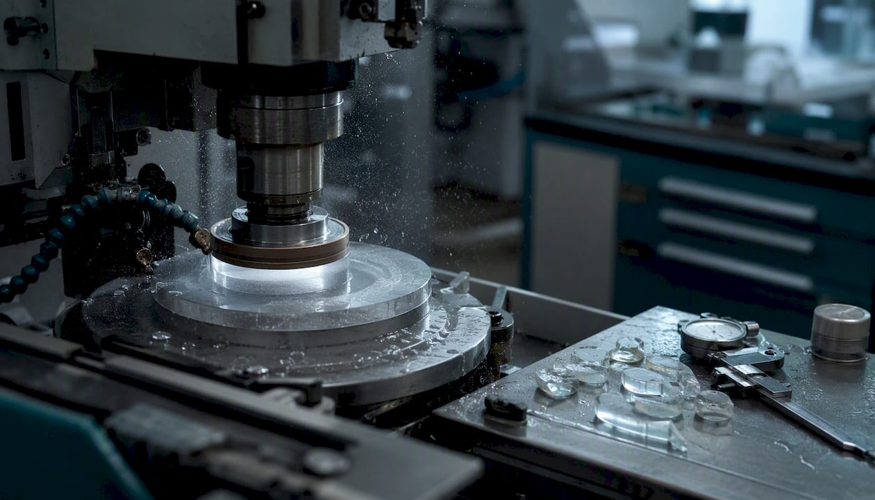
Generating uses diamond-bonded cup wheels or ring tools to remove bulk material and establish the basic radius of curvature or flat. Fixed-abrasive CNC generating machines can hold form to within a few micrometres and have largely replaced loose-abrasive ring grinding for production work. Coarse grinding follows, stepping through successively finer grits (typically 60 to 400 mesh) to reduce subsurface damage depth before lapping begins. The depth of subsurface damage after grinding scales with grit size, so skipping grit grades to save time usually costs more in polishing.
Lapping and conventional polishing
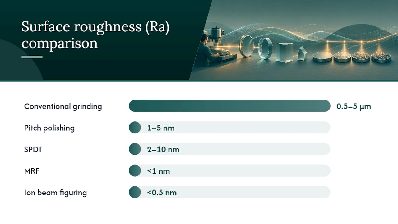
Lapping with loose aluminium oxide or silicon carbide slurry on a cast-iron tool removes the subsurface damage layer and brings the surface to within a few micrometres of final figure. Conventional pitch polishing with cerium oxide slurry then achieves surface roughness in the 1–5 nm Ra range and figure errors at λ/10 P-V for spherical surfaces. The pitch tool conforms to the surface and averages out mid-spatial-frequency errors, which is both its strength and its limitation: it cannot correct localised figure errors without introducing new ones elsewhere.
Single-point diamond turning
Single-point diamond turning (SPDT) machines aluminium, copper, and certain crystalline substrates directly to optical finish without polishing. Achievable roughness is typically 2–10 nm Ra, and form accuracy of λ/4 to λ/10 P-V is routine on axis-symmetric surfaces. SPDT is the preferred route for infrared optics in germanium and silicon, and for aluminium mirror substrates used in defence and aerospace applications. It does not suit glass or ceramics, which fracture under the cutting forces.
Magnetorheological finishing and ion beam figuring
MRF uses a magnetically stiffened slurry ribbon to remove material deterministically from a computer-controlled removal map. It introduces negligible subsurface damage and can correct figure errors to better than λ/50 RMS, making it the method of choice for high-power laser optics and aspheres where conventional polishing leaves residual mid-spatial-frequency errors. The SPIE Field Guide to Optical Fabrication notes that the choice between conventional polishing and MRF often turns on the risk of subsurface damage and the need for deterministic removal on complex surfaces.
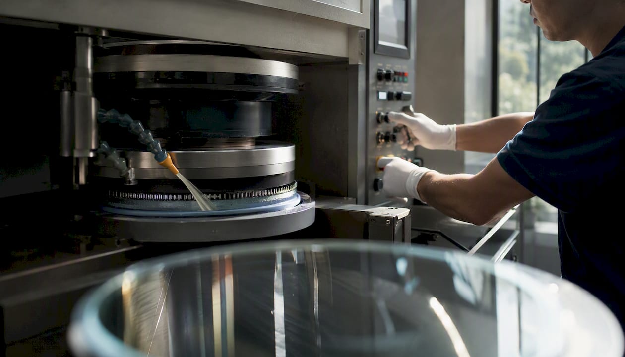
Ion beam figuring removes material atom by atom using a focused ion beam, achieving sub-nanometre figure corrections on surfaces that are already near-final. It is slow and expensive, but it is the only method that can correct a surface without any mechanical contact or risk of edge roll-off. IBF is typically reserved for the final correction step on large telescope mirrors, high-precision flats, and extreme-UV optics.
| Method | Typical figure (P-V) | Roughness (Ra) | Best suited to | Key limitation |
|---|---|---|---|---|
| Conventional grinding | 5–50 µm | 0.5–5 µm | Bulk removal, all materials | Subsurface damage |
| Pitch polishing | λ/10 | 1–5 nm | Spheres, flats, glass | Cannot correct local errors |
| SPDT | λ/4–λ/10 | 2–10 nm | IR metals, crystals | Not suitable for glass |
| MRF | λ/50 RMS | < 1 nm | Aspheres, laser optics | Capital-intensive |
| Ion beam figuring | < λ/50 | < 0.5 nm | Final correction, large optics | Very slow, high cost |
Pro Tip: When specifying MRF, confirm that your substrate material is compatible with the MR fluid chemistry. Some optical crystals and certain coated pre-forms react with the carbonyl-iron carrier fluid and require a protective pre-coat or an alternative finishing route.
Which optical materials suit which fabrication routes?
Material choice is not just an optical decision. Hardness, thermal expansion coefficient, anisotropy, and chemical reactivity all constrain which fabrication routes are viable and what coating systems will adhere reliably.
Optical glasses and fused silica
Soda-lime glass is inexpensive and widely available as float-process ribbon. The float process yields flat, fire-finished ribbon with thicknesses from sub-millimetre to around 25 mm, making it the standard substrate for display glass, scanner windows, and protective covers. Borosilicate glass (Schott BOROFLOAT or equivalent) offers lower thermal expansion and better chemical resistance, suiting it to laboratory and medical applications. BK7-type optical crown glass remains the workhorse for visible-band lenses and windows: it polishes readily, accepts most anti-reflection coating systems, and is available in fine-annealed and precision-annealed grades.
Fused silica is the substrate of choice for UV and deep-UV applications. Its near-zero thermal expansion and high UV transmission come at the cost of harder machining: it requires finer grit progression and longer polishing cycles than BK7. Glass production involves annealing in a lehr to relieve internal stress, and for fused silica this step is particularly critical because residual stress birefringence directly degrades wavefront quality.
Crystalline substrates
Calcium fluoride (CaF2) and barium fluoride (BaF2) are used for deep-UV and IR windows. Both are soft and cleave readily, so they require careful fixturing and gentle polishing with non-aqueous slurries. Sapphire is extremely hard (Mohs 9) and requires diamond abrasives throughout; it polishes to excellent scratch-dig values and is used for sensor windows in defence and aerospace where mechanical durability is paramount. Silicon and germanium are the standard IR substrates and are almost always diamond-turned rather than conventionally polished, because SPDT achieves optical finish in a single operation.
Ceramics and polymer optics
Zerodur and ULE (ultra-low expansion) glass-ceramics are used for mirror substrates in applications where dimensional stability over temperature is critical, such as space telescopes and precision metrology instruments. They machine similarly to hard optical glass but require careful stress-relief cycles. Polymer optics, typically injection-moulded PMMA or polycarbonate, are produced by precision moulding rather than grinding and polishing; post-mould diamond turning or single-point turning can improve surface figure where the mould alone is insufficient.
For deeper reading on material selection for glass components, including procurement lead times and handling requirements, Precision Glasses publishes a dedicated engineer’s guide.
| Material | Typical fabrication route | Coating compatibility | Procurement note |
|---|---|---|---|
| Soda-lime float | Grinding, polishing | Standard AR, mirror | Short lead time, wide availability |
| BK7 / optical crown | Grinding, pitch polish, MRF | All standard coatings | Stock available; fine-annealed to order |
| Fused silica | Grinding, CNC polish, MRF, IBF | UV-grade AR, BBAR | Longer lead time; stress-relief critical |
| CaF2 / BaF2 | Gentle polishing, non-aqueous slurry | Limited; specialist coatings | Long lead time; fragile handling |
| Sapphire | Diamond grinding, fine polish | Hard oxide coatings | Moderate lead time; high tooling cost |
| Silicon / Germanium | SPDT | IR AR coatings | Stock blanks; SPDT turnaround 2–4 weeks |
| Zerodur / ULE | CNC grinding, fine polish, IBF | Specialist reflective | Long lead time; stress-relief mandatory |
Key material selection points:
- Confirm the thermal expansion coefficient against your operating temperature range before committing to a substrate.
- Check coating adhesion data for the specific glass-coating combination, not just the generic material class.
- For crystalline substrates, request orientation certificates from the blank supplier; anisotropy affects both machining behaviour and transmitted wavefront.
How fabrication differs by optic type
Geometry drives process selection as much as material does. The same surface accuracy target costs very different amounts of time and money depending on whether the surface is flat, spherical, aspheric, or free-form.
Plane optics (flats, windows, beam splitters, prisms) are the most straightforward to fabricate. Conventional lapping and polishing on a flat reference tool achieves flatness to λ/10 or better. Large flats above 300 mm diameter require stress-free mounting during polishing to avoid print-through of the support structure into the finished surface.
Spherical optics (lenses, concave and convex mirrors) benefit from the self-correcting geometry of the spherical tool: a convex surface and a concave tool of the same radius will lap to a perfect sphere if run long enough. This makes spherical optics the most cost-effective geometry for high-accuracy surfaces, and conventional polishing can reach λ/20 P-V with careful process control.
Aspheres and free-form surfaces cannot be corrected by a conforming tool. They require:
- CNC-generated starting form to within a few micrometres of final figure.
- Sub-aperture polishing (MRF, small-tool CNC polishing) to correct residual figure errors.
- Interferometric verification against a computer-generated hologram (CGH) or null lens at each correction cycle.
- Typically two to four MRF correction cycles to reach λ/10 RMS or better.
Large optics (above 500 mm) introduce handling and support challenges that dominate the process plan. Stress relief after rough machining is mandatory; the blank must be supported on a kinematic mount during polishing to avoid gravity-induced figure errors. Segmented mirror assemblies add alignment and co-phasing requirements on top of individual segment figure tolerances.
IR optics in germanium or silicon are almost always SPDT, regardless of geometry, because the material responds well to diamond turning and the IR wavelength band tolerates the 2–10 nm Ra roughness that SPDT produces.
Specifications and tolerances every engineer must define
A specification that cannot be tested is not a specification. Every tolerance on an optical drawing should map directly to a measurement method and an acceptance criterion. The ISO 10110 family of standards provides the drawing notation; the descriptions below explain what each parameter means in practice.
Surface figure describes how closely the finished surface matches the intended form. It is expressed as wavefront error (because the wavefront is what matters to system performance) in either peak-to-valley (P-V) or RMS. RMS is the more meaningful metric for system modelling: a surface with λ/4 P-V but most of the error in low-order terms will perform very differently from one with λ/4 P-V concentrated in mid-spatial frequencies.
Surface roughness (Ra or RMS) describes the fine-scale texture of the surface and drives scatter losses. For visible-band imaging, Ra below 1 nm is typical; for high-power laser optics, Ra below 0.5 nm RMS is often specified to limit laser-induced damage. Power spectral density (PSD) is increasingly used alongside Ra to characterise the spatial frequency content of roughness.
Scratch-dig is the US MIL-PRF-13830B notation still widely used in procurement. A scratch-dig of 80-50 is standard for non-critical surfaces; 20-10 is demanded for high-power laser optics. Understanding scratch-dig specifications is important because the numbers are not roughness values: they are visual quality grades assessed under controlled illumination.
Wedge and parallelism matter for windows and beam splitters where angular deviation of the transmitted beam must be controlled. Wedge is typically expressed in arc minutes or arc seconds.
Centration (or decentration) describes how well the optical axis of a lens aligns with its mechanical axis, expressed in arc minutes or as a lateral offset in micrometres.
Pro Tip: Write tolerances in pairs: the value and the test method. “Surface figure: λ/10 P-V at 633 nm, measured by Fizeau interferometer against a calibrated reference flat” is a testable specification. “Surface figure: λ/10” alone leaves the test method open to interpretation and creates the conditions for a delivery dispute.
Metrology and acceptance testing for optical components
Metrology is not the final step; it is the feedback loop that makes deterministic fabrication possible. Without traceable measurement at each process stage, finishing is guesswork.
Interferometry is the primary tool for surface figure measurement. A Fizeau interferometer compares the test surface against a reference flat or sphere and produces a full-aperture wavefront map. Phase-shifting interferometry (PSI) improves measurement repeatability by averaging multiple phase-shifted frames. For aspheres and free-form surfaces, null optics or computer-generated holograms are placed in the beam path to compensate the nominal departure from a sphere, allowing the interferometer to measure only the residual error.
Profilometry covers both contact (stylus) and non-contact (white-light interferometry, confocal) methods for surface roughness measurement. Stylus profilometry is traceable and well-understood but risks scratching soft substrates; white-light interferometry is faster and non-contact, making it the preferred method for production environments.
Scatter measurement using total integrated scatter (TIS) or bidirectional reflectance distribution function (BRDF) instruments quantifies scatter losses that interferometry cannot detect. For laser optics and anti-reflection coatings, scatter measurement is a mandatory acceptance test.
Environmental and functional testing includes:
- Thermal cycling to verify coating adhesion and substrate stability.
- Humidity and salt-fog exposure for defence and marine applications.
- Laser damage threshold (LDT) testing to ISO 21254 for high-power laser optics.
- Coating spectrophotometry to verify transmission and reflection curves against specification.
All metrology equipment used in acceptance testing should carry UKAS-traceable calibration certificates. UKAS accreditation (the UK’s national accreditation body) is the standard demanded by defence and aerospace procurement and should be specified explicitly in the purchase order. Pilkington’s float lines demonstrate the value of automated inline inspection for continuous production: integrating measurement into the production line rather than reserving it for end-of-line acceptance reduces scrap and accelerates throughput.
Acceptance tests to request in a specification:
- Full-aperture interferogram with wavefront map and RMS/P-V values.
- Surface roughness report (Ra and RMS) from calibrated profilometer.
- Scratch-dig inspection report under MIL-PRF-13830B or equivalent.
- Dimensional inspection report (diameter, thickness, radius of curvature, wedge, centration).
- Coating spectrophotometry report with pass/fail against specification.
- UKAS-traceable calibration certificates for all measurement instruments used.
End-to-end fabrication workflow, lead times, and cost drivers
A well-managed precision glass manufacturing workflow follows a logical sequence with defined hold points for inspection before the component moves to the next operation.
Typical workflow steps:
- Design for manufacture review: confirm tolerances are achievable with available process capability; flag any conflicts between surface figure, coating, and dimensional requirements.
- Blank procurement and incoming inspection: verify material grade, stress birefringence, and dimensional allowance for machining.
- Generating: establish radius of curvature or flat to within 5–10 µm of nominal.
- Coarse and fine grinding: step through grit grades to reduce subsurface damage.
- Lapping: bring surface to within 1–2 µm of final figure.
- Polishing (conventional or MRF): achieve target figure and roughness; interferometric check after each cycle.
- Coating: apply AR, reflective, or functional coating; spectrophotometric verification.
- Assembly (where applicable): mount into housing, align, and verify system wavefront.
- Final acceptance test: full inspection report against drawing tolerances.
- Packing and delivery: stress-free packaging with traceability documentation.
Typical lead times:
- Small precision lenses (< 50 mm, standard glass, conventional polish): 4–8 weeks.
- Aspheres requiring MRF correction cycles: 8–14 weeks.
- Large optics (> 300 mm) or segmented assemblies: 16–26 weeks or longer.
- Special substrates (CaF2, Zerodur, sapphire): add 4–12 weeks for blank procurement.
- Coatings on specialist substrates: add 2–4 weeks.
Major cost drivers:
- Surface figure target: each step tighter than λ/10 P-V adds significant polishing and metrology time.
- Material: fused silica, CaF2, and Zerodur blanks cost an order of magnitude more than BK7.
- Batch size: unit cost drops sharply above 10–20 pieces as set-up costs are amortised.
- Coating complexity: broadband AR coatings are straightforward; high-reflectance laser coatings and environmental coatings for defence add cost and lead time.
- Traceability requirements: full batch-level traceability with serialised inspection records adds documentation overhead.
Procurement specification checklist:
- Drawing to ISO 10110 with all tolerances explicitly stated and test methods named.
- Material grade and stress birefringence limit.
- Coating specification with spectrophotometric acceptance criteria.
- Required inspection reports and traceability level (batch or serial number).
- Packaging and handling requirements.
- Delivery schedule with hold points for witness inspection if required.
Standards, quality systems, and UK compliance considerations
Specifying the right standards at the outset removes ambiguity from acceptance and protects both parties in a procurement dispute.
ISO 10110 is the primary international standard family for optical drawing notation. It covers material imperfections, surface form tolerances, surface imperfection tolerances (scratch-dig), coating requirements, and assembly tolerances. Using ISO 10110 notation on drawings is the clearest way to communicate optical tolerances to a fabricator.
ISO 4287 and ISO 4288 (now largely superseded by ISO 21920 for surface texture) define the parameters and measurement conditions for surface roughness. When specifying Ra or Rq, reference the relevant ISO standard and state the cut-off wavelength to avoid ambiguity.
ISO 21254 governs laser-induced damage threshold testing for optical components and coatings. Specify the relevant part (1-S-on-1, N-on-1, or ramp test) and the wavelength and pulse duration for your application.
ISO 9001 quality management system certification is a baseline expectation for defence and aerospace supply chains. For medical device applications, ISO 13485 is the relevant quality system standard.
UKAS accreditation: the United Kingdom Accreditation Service is the sole national accreditation body recognised by the UK government. Specifying UKAS-traceable calibration for all measurement instruments used in acceptance testing is the correct requirement for UK defence and aerospace procurement. Certificates should state the calibration date, the reference standard used, and the measurement uncertainty.
Documentation to demand on delivery:
- Dimensional inspection report with instrument identification and calibration reference.
- Surface figure interferogram with wavefront map, RMS, and P-V values.
- Coating spectrophotometry report.
- Material certificate with melt number or batch reference.
- UKAS-traceable calibration certificates for all instruments used.
- Conformance statement against drawing revision and issue.
For sector-specific quality requirements in defence, medical, and aerospace, Precision Glasses maintains a quality management framework that addresses documentation, traceability, and compliance certification for each sector.
How Precision Glasses executes an optical fabrication project
The following describes a representative project path for a custom precision optical component at Precision Glasses, from initial enquiry through to delivery.
Project workflow:
- Technical enquiry: the client submits a drawing (ISO 10110 preferred), material specification, quantity, and environmental requirements. Precision Glasses reviews for manufacturability and flags any tolerance conflicts before quoting.
- Material selection and blank procurement: the team selects the appropriate substrate grade and places a blank order with incoming inspection against the material certificate.
- CNC machining and generating: blanks are generated to radius and diameter using CNC grinding, with form checked against the drawing at this stage.
- Grinding and lapping: subsurface damage is progressively removed through grit grades; lapping brings the surface to within specification for polishing.
- Polishing and figure verification: conventional polishing or MRF is applied depending on the figure target; interferometric verification is performed after each polishing cycle.
- Coating: anti-reflection, mirror, or functional coatings are applied and verified by spectrophotometry.
- Final acceptance and documentation: a full inspection report is generated, covering all drawing tolerances, with UKAS-traceable calibration references for each measurement.
- Packing and delivery: components are packed to prevent stress and surface damage; traceability documentation travels with the shipment.
Precision Glasses serves defence, aerospace, medical device, automotive, and electronics sectors from its UK base, with batch-level traceability and bespoke tolerance management as standard for demanding procurement contracts.
To accelerate quoting, include the following in your technical enquiry to Precision Glasses:
- ISO 10110 drawing or equivalent with all tolerances stated.
- Material grade and any stress birefringence or homogeneity requirements.
- Coating specification with spectrophotometric acceptance criteria.
- Required quantity and batch size.
- Environmental and sector compliance requirements (defence, medical, aerospace).
- Delivery schedule and any witness inspection requirements.
What experience teaches about optical fabrication projects
The projects that run smoothly share one characteristic: the specification was written by someone who understood what could be tested. The projects that generate rework almost always trace back to a tolerance that was tighter than necessary, or a test method that was left undefined.
A few lessons that apply consistently across fabrication programmes:
- Prioritise figure over roughness in the first instance. You can improve roughness with a final polishing step; you cannot easily correct figure without a full MRF cycle. Set the figure target first, then ask whether the roughness requirement is genuinely driven by the application or by habit.
- Stage your verification. An interferometric check after lapping costs a fraction of what a full MRF correction cycle costs. Build hold points into the process plan rather than discovering figure errors at final inspection.
- Check material early. Stress birefringence and homogeneity defects in the blank cannot be corrected by polishing. Incoming inspection of the blank, including polarimetric stress measurement, is cheap insurance against scrapping a finished component.
- Write tolerances that are testable. As the Edmund Optics specification guidance makes clear, clear specification language that ties tolerances to test methods reduces disputes and rework.
On the technology side, MRF adoption has matured considerably over the past decade. It is no longer a specialist process reserved for telescope mirrors; it is available from a growing number of UK and European fabricators for components above roughly 20 mm diameter. Inline metrology, where interferometric or profilometric measurement is integrated into the polishing machine rather than performed as a separate step, is the next significant productivity gain. Several CNC polishing platforms now offer closed-loop figure correction, reducing the number of separate measurement cycles and shortening lead times for aspheric components. The practical adoption timeline for inline closed-loop polishing in volume production is likely within the next three to five years for mid-tier fabricators.
Precision Glasses: specification-driven optical fabrication in the UK
Engineers working on demanding programmes in defence, aerospace, medical devices, and electronics need a fabrication partner who reads a drawing the same way they wrote it. Precision Glasses offers custom optical components and assemblies manufactured to specification, with UKAS-traceable metrology, full batch traceability, and compliance documentation as standard.

We work from your ISO 10110 drawing or equivalent specification, manage blank procurement, machining, polishing, coating, and final acceptance testing under one roof, and deliver with a full inspection report. Our sector experience spans defence sensor windows, medical device cover glass, aerospace display glass, and precision optical assemblies for scientific instrumentation. For programmes where lead time and first-article success rate matter, the right conversation to have is before the drawing is finalised. Send your technical enquiry, including your drawing, material requirements, quantities, and environmental specification, to Glassprecision and we will review for manufacturability and return a detailed quotation.
Sources
The sources below are the most reliable starting points for formal definitions, process detail, and standards compliance.
- Field Guide to Optical Fabrication | (2011) | Williamson | Publications | SPIE
- Primary Fabrication of Flat Glass – Encyclopedia of Glass Science, Technology, History, and Culture – Wiley Online Library
- The Float Process Step by Step
- Optical manufacturing and testing


