
Defects in precision glass components do not simply mean rework costs. In defence optics, medical imaging, or aerospace sensors, a single out-of-tolerance lens can ground a programme or compromise patient safety. Engineers and procurement managers in these sectors face relentless pressure to source components that meet tighter specifications than ever, with shorter lead times and no margin for yield failures. This guide walks you through the entire precision glass manufacturing workflow, from preform selection to final verification, with concrete technical detail designed to help you optimise processes, reduce scrap, and specify components with confidence.
Table of Contents
- Understanding precision glass manufacturing: The essentials
- Preparation: Tools, materials, and workflow prerequisites
- Step-by-step workflow: Delivering high-precision glass components
- Troubleshooting and error compensation in manufacturing
- Measuring success: Verification and industry benchmarks
- Precision glass workflows: What typical guides miss (and why it matters)
- Take your precision glass manufacturing further with expert support
- Frequently asked questions
Key Takeaways
| Point | Details |
|---|---|
| Workflow precision matters | Each step in glass manufacturing must be tightly controlled to meet advanced application standards. |
| PGM enables complex shapes | PGM delivers replicable, cost-effective aspheres and freeforms not feasible by grinding or polishing. |
| Preparation prevents failure | Investing in proper tools, materials, and coatings avoids sticking and process interruptions. |
| Measurement drives quality | Continuous verification against industry benchmarks ensures high yield, low scrap, and performance. |
Understanding precision glass manufacturing: The essentials
Precision glass manufacturing refers to controlled production of glass components where dimensional accuracy, surface quality, and optical performance are specified to tolerances that conventional glass processing cannot reliably achieve. It is not simply polishing a glass blank. It is an end-to-end system of matched materials, controlled environments, and validated process steps.
The dominant advanced method is precision glass moulding (PGM). PGM replaces slow, labour-intensive grinding and polishing cycles with a direct pressing approach: a precision-shaped glass preform is heated above its transition temperature and pressed between matched moulds to produce the finished geometry in a single thermal cycle. Precision glass moulding is suitable for lenses up to 60 mm diameter, with specific requirements for shape and process steps, making it well-suited to micro-optics, aspheric lenses, and freeform optical surfaces that would otherwise require extensive manual finishing.
The core workflow stages across both PGM and traditional precision methods include:
- Preform production: Selection or fabrication of a glass blank with the correct volume, chemistry, and surface condition
- Thermal forming or grinding: Shaping the glass to its near-net geometry
- Surface finishing: Polishing, lapping, or direct mould release to achieve target roughness
- Verification and metrology: Dimensional, surface, and optical inspection against specification
PGM’s primary advantage over conventional precision glass fabrication is its suitability for aspheric and freeform geometries at production volumes. Grinding and polishing aspheric surfaces is time-consuming and highly skill-dependent. PGM removes those variables by encoding the geometry into the mould, which can be replicated to sub-micron consistency across thousands of cycles.
| Feature | Conventional grinding and polishing | Precision glass moulding (PGM) |
|---|---|---|
| Aspheric capability | Limited, high cost | Excellent, design-driven |
| Cycle time per part | Minutes to hours | Under 90 seconds |
| Surface roughness achievable | 5–10 nm Ra | Below 5 nm Ra |
| Minimum skilled labour dependency | High | Moderate |
| Scrap rate (typical) | 3–8% | Below 1% |
For defence, aerospace, medical device, and automotive sensor applications, PGM is the benchmark. However, material and process constraints apply. Not all glass types are suitable: low transition temperature glasses (Tg below approximately 600°C) are preferred for mould longevity and process control.
Preparation: Tools, materials, and workflow prerequisites
With the basics understood, the next step is ensuring every workflow starts with the correct setup. Poor preparation is the leading cause of preventable yield loss. Before a single preform enters the press, several prerequisites must be in place.
Technical glass materials selection is the first critical decision. The glass must have a stable, well-characterised thermal expansion coefficient, compatible chemistry with mould materials, and adequate homogeneity. Common choices include borosilicate glass, chalcogenide glass for infrared applications, and low-Tg optical glasses designed specifically for PGM.
Environmental and machine controls are non-negotiable. Advanced glass specifications for PGM require that machines control temperature within ±0.5°C, with mould surface roughness below 5 nm Ra to ensure the finished part inherits the mould’s geometric quality.
Key environmental requirements include:
- Nitrogen atmosphere throughout heating, pressing, and initial cooling to prevent oxidation of mould coatings and glass surfaces
- Thermal stability in the pressing zone with no uncontrolled draughts, vibration, or thermal gradients from adjacent equipment
- Cleanroom-standard handling areas to prevent particulate contamination of preforms before moulding
- Validated preform inspection protocol covering surface condition, geometry, and mass tolerance before loading
Mould preparation is equally important. Silicon carbide and tungsten carbide moulds are typical substrate choices, offering the hardness and stability needed for repeated thermal cycling. Without an appropriate release coating, glass will bond to the mould surface during pressing.
Pro Tip: Apply platinum or iridium PVD (physical vapour deposition) coatings to mould surfaces before production runs. These coatings prevent glass sticking and resist chemical reaction at moulding temperatures, significantly extending mould life and protecting surface finish consistency.
A structured pre-production checklist avoids the majority of setup-related defects. Verify mould coating integrity, confirm furnace temperature calibration, check preform dimensions and surface cleanliness, and validate nitrogen supply and purity before commencing any batch.
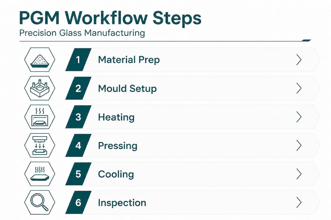
Step-by-step workflow: Delivering high-precision glass components
Once all preparations are complete, execution depends on following every workflow stage with the precision the process demands. Here is the complete PGM sequence with technical parameters for each stage.
Preform preparation. Select or fabricate a glass preform with the correct volume (typically within ±1% of target) and a surface finish better than 10 nm Ra. Clean with ultrasonic and chemical methods to remove all organic contamination. Weigh and record each preform. Dimensional variation at this stage carries directly into the finished component.
Loading and atmospheric purging. Place the preform into the lower mould. Seal the press chamber and purge with high-purity nitrogen. Oxygen levels must be below a defined threshold (commonly below 10 ppm) before heating begins. This step protects both the glass and the mould coating.
Heating. Ramp the furnace to the target moulding temperature, typically 10–100°C above the glass transition temperature. Heating rate is controlled to avoid thermal shock and ensure the preform reaches a uniform, stable viscosity throughout. Uneven heating creates form errors in the pressed part.
Pressing: Travel-controlled phase. The upper mould descends at a controlled rate until it contacts the softened glass. This initial travel phase positions the mould precisely before force is applied. Speed is kept low to avoid trapping gas at the glass-mould interface, which would create surface defects.
Pressing: Force-controlled phase. Once contact is confirmed, the press switches to force control. A programmed force profile maintains forming pressure for a defined dwell time, ensuring the glass fully conforms to the mould geometry. This phase determines final shape accuracy.
Cooling under load. The PGM process delivers micro-optics in under 90 seconds per cycle, but controlled cooling under maintained nitrogen protection is essential to avoid stress birefringence and surface degradation. Cooling rate is matched to the glass type’s annealing curve.
Demoulding. Once the glass has cooled below the strain point, the press opens and the component is removed. Bi-concave geometries present elevated sticking risk at this stage due to the geometry engaging both mould surfaces simultaneously. Adapted demoulding forces and tool geometry are required for these shapes.
Note: Bi-concave lens shapes are particularly susceptible to mould sticking during demoulding due to simultaneous contact across two concave surfaces. If your specification includes bi-concave forms, design your handling and demoulding protocol specifically for this geometry, and monitor mould coating condition more frequently.
- Post-mould finishing (where required). For most PGM optics, minimal finishing is needed. Anti-reflection coatings, edge grinding, or centring may follow, depending on specification.
Fabrication process steps executed correctly and consistently can achieve scrap rates as low as 0.8%, with shape accuracy to ±2 μm, benchmarks that directly affect programme cost and delivery reliability.
Pro Tip: Log temperature profiles, force curves, and nitrogen consumption data for every batch. When a deviation occurs, this data allows you to pinpoint the step where the process diverged, rather than conducting lengthy investigations after the fact.
Troubleshooting and error compensation in manufacturing
No matter how optimised the workflow, challenges arise. The following techniques support rapid, accurate diagnosis and correction of common PGM deviations.
Common sources of defects in precision glass workflows include:
- Thermal non-uniformity leading to asymmetric form errors
- Mould coating degradation causing surface contamination or sticking
- Preform dimension variance introducing volume errors in the final part
- Atmospheric control failure producing surface oxidation or haze
- Non-isothermal moulding conditions which, without compensation, exacerbate form inaccuracies
For yield improvement and consistent output, process engineers should implement structured error compensation rather than relying purely on trial-and-error mould adjustments.
Surrogate models such as BPNN (back-propagation neural networks) can hold form errors below 2 μm by predicting the mould geometry correction needed to account for elastic springback and thermal contraction in the glass after pressing. These models are trained on historical process data and updated as new results come in. The result is predictive compensation that goes beyond what empirical tuning alone can achieve.
Drilling and machining operations, sometimes required for mounting features or assembly interfaces, also introduce risk. Mechanical drilling produces chipping of 10–50 μm at hole edges, while laser techniques reduce chipping to 0.25 μm. For components where edge integrity is critical to sealing or optical alignment, laser processing is the correct choice.
| Problem | Likely cause | Recommended corrective action |
|---|---|---|
| Form error exceeding ±2 μm | Thermal non-uniformity or springback | Apply surrogate model compensation to mould geometry |
| Surface haze or oxidation | Atmospheric contamination | Verify nitrogen purity and chamber seal integrity |
| Sticking during demoulding | Coating degradation or geometry | Inspect and recoat mould; adapt demoulding force profile |
| Edge chipping | Mechanical post-processing | Switch to laser drilling or cutting for critical features |
| Volume-related shape error | Preform mass variance | Tighten preform weighing tolerance and reinspect incoming stock |
Review quality benchmarks regularly. Comparing actual process output against accepted benchmarks is the clearest indicator of whether a corrective action has been effective.
Measuring success: Verification and industry benchmarks
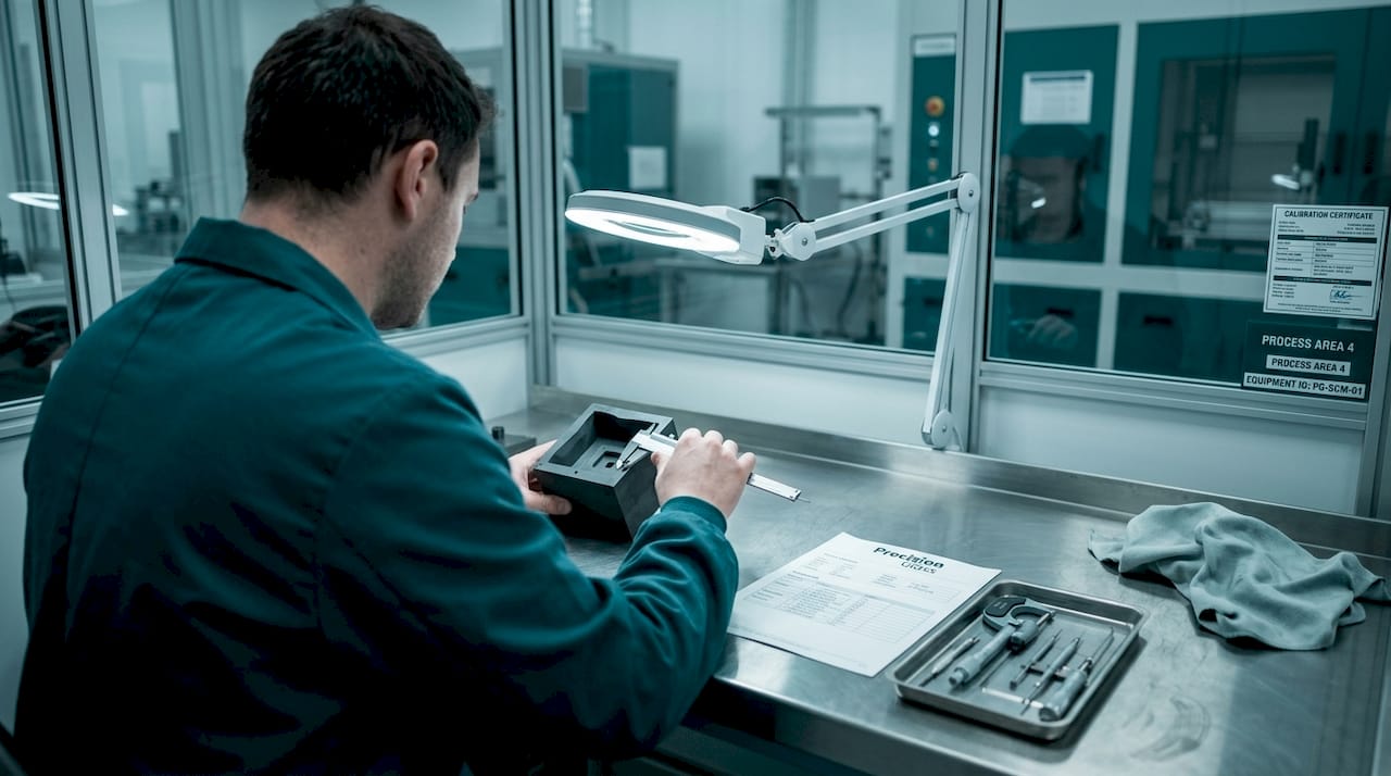
Following troubleshooting and compensation, final quality depends on robust measurement, both for batch release and ongoing process improvement. Verification is not a final gate; it is a data-collection step that feeds back into the process.
The core measurement parameters for precision glass components are:
- Surface roughness (Ra): Measured with interferometry or atomic force microscopy. Target is below 5 nm Ra for optical surfaces.
- Form accuracy: Measured with a coordinate measuring machine (CMM) or interferometer. PGM routinely delivers shape accuracy of ±2 μm and surface roughness below 5 nm Ra, with scrap rates below 1%.
- Scrap rate: Tracked per batch and per mould cycle count.
- Centration and edge geometry: Critical for lens assemblies and mounting interfaces.
- Birefringence: Assessed with polarimetry to verify that the annealing protocol has adequately relieved stress.
Pro Tip: Integrate inline metrology wherever possible. Real-time surface roughness and form measurement, fed directly to the process control system, enables immediate correction before a full batch is produced to a non-conforming specification. This single investment typically reduces scrap more than any single parameter adjustment.
| Metric | Typical industry performance | Best-in-class PGM |
|---|---|---|
| Surface roughness (Ra) | 5–10 nm | Below 5 nm |
| Shape tolerance | ±5 μm | ±2 μm |
| Scrap rate | 2–5% | Below 1% |
| Cycle time (micro-optics) | 3–10 minutes | Under 90 seconds |
For micro-optics below 5 mm diameter, measurement instrumentation must be selected carefully: standard CMM probe contact can damage surfaces. Non-contact interferometric methods are standard for optical glass design verification at this scale. For larger aspheres, subaperture stitching interferometry is the method of choice, enabling full-surface measurement of complex geometries without contact. Reviewing industry specifications for your target application ensures measurement plans are aligned with what the end-use environment actually demands.
Precision glass workflows: What typical guides miss (and why it matters)
Most process guides focus on individual steps: correct temperature here, correct force there. This is necessary but not sufficient. From our experience working with defence, aerospace, and medical device programmes, the real differentiator between a reliable production line and a persistent yield problem is workflow coherence, not the performance of any single parameter in isolation.
Consider mould coating management. Guides mention platinum or iridium PVD as best practice. What they rarely address is the discipline of tracking coating condition across mould cycles, correlating coating wear with form error trends, and having a validated recoating protocol before problems appear. Small lapses in this discipline compound quietly, and the defects surface weeks later when tracing the root cause becomes genuinely difficult.
The same logic applies to cleanroom handling. Particulate contamination on a preform does not necessarily cause an obvious visible defect; it may cause a subtle surface scatter that only appears during final optical testing. Tightening handling discipline is not glamorous process engineering, but it is frequently the most cost-effective yield improvement available.
We also see underinvestment in cross-functional training. Metrology technicians who understand PGM thermal physics and process engineers who understand interferometric measurement communicate far more effectively when issues arise. The engineering basics that support a shared understanding between disciplines are worth embedding in team training programmes, not just in technical documentation that rarely gets read under production pressure.
Finally, AI-enhanced error compensation via surrogate models is not a future capability. It is available now and already deployed in best-in-class operations. Teams that treat it as an optional advanced feature are leaving measurable yield and quality gains on the table.
Take your precision glass manufacturing further with expert support
Precision Glasses works with engineers and procurement teams across defence, aerospace, medical devices, automotive, and electronics to deliver glass components built to the exact specifications each application demands.

Whether you are specifying a complex aspheric lens, sourcing technical glass products for a new programme, or reviewing your supply chain for reliability, our team brings manufacturing expertise and meticulous quality assurance to every project. From initial design support through prototyping and volume supply, we tailor our process to your requirements, not the other way around. Explore our range of optical glass components or contact us directly to discuss your specification. Visit Precision Glasses to learn more about our capabilities and request a tailored quote.
Frequently asked questions
What is the typical cycle time for producing micro-optics via precision glass moulding?
Cycle times can be under 90 seconds for micro-optics using precision glass moulding machines, making PGM one of the fastest routes to finished optical components at production volumes.
How do you minimise the risk of glass sticking to moulds?
Apply platinum or iridium PVD coatings to mould surfaces; these coatings minimise sticking and prevent chemical reaction between glass and mould substrate during pressing.
What measurement accuracy is achievable in precision glass manufacturing workflows?
Shape accuracy of ±2 μm and surface roughness below 5 nm Ra are achievable industry standards with correctly configured PGM workflows and calibrated metrology.
How is process error compensated in PGM workflows?
Surrogate models such as BPNN compensate for form errors by predicting the mould geometry corrections needed to account for springback and thermal contraction, routinely keeping errors below 2 μm.
Is precision glass moulding suitable for both convex and concave glass shapes?
Bi-convex shapes are the most straightforward to produce; bi-concave geometries present elevated sticking risk during demoulding and require adapted handling protocols and more frequent mould coating inspection.
Recommended
- Glass fabrication: Precision processes for critical industries – Precision Glass
- How to optimise glass sourcing for precision: 5 key steps – Precision Glass
- How to design optical glass: expert steps for precision results – Precision Glass
- Glass engineering basics: Foundations for high-precision sectors – Precision Glass
- Streamline lab consumables workflow: a guide for managers