
For engineered glass prototypes, maskless ultrafast laser micromachining and targeted glass additive manufacturing deliver functional parts fastest, chosen by geometry complexity and optical tolerance. When wavefront accuracy or a polished surface finish matters more than speed, conventional CNC machining and hand polishing still win. Supports both routes, with prototype-to-volume manufacturing that carries a design through to production runs without a second supplier search.
TL;DR:
- Laser micromachining offers fast, maskless fabrication for microfeatures, but is limited by slow serial processing and surface finish quality requiring additional polishing.
- Additive manufacturing methods excel at producing complex internal channels and monolithic geometries but typically result in lower optical clarity and internal stresses needing post-processing.
- CNC machining and casting methods provide tighter tolerances, better optical surfaces, and quicker turnaround for simple, precision parts, often outperforming additive methods in speed and cost.
- Post-processing steps such as annealing, polishing, and coating are critical for functional, optical-ready prototypes and can significantly add to overall costs.
- Proper planning involves defining critical tolerances, test purposes, and batch size upfront, with supplier verification of metrology and traceability being essential for regulated or high-precision projects.
Table of Contents
- What is rapid prototyping glass and which methods qualify?
- How fast is laser-based micromachining for glass prototypes?
- Can 3D printing produce functional glass prototypes?
- When do CNC machining, waterjet, and casting beat 3D printing?
- Why post-processing decides whether a glass prototype actually works
- How do you choose the right rapid prototyping route?
- How Precision Glasses supports rapid prototyping and scale-up
- Can you embed electrodes or sensors during glass prototyping?
- How do mechanical and optical properties compare across methods?
- What does rapid glass prototyping cost by method?
- How do you test a rapid prototyped glass part?
- Author perspective: choosing prototypes that de-risk the project
- Ready to move from prototype to production glass parts?
- Primary sources and recommended further reading
- Sources
- FAQ
What is rapid prototyping glass and which methods qualify?
Rapid prototyping glass covers any fabrication method that turns a design into a working glass part in days or weeks rather than months. Seven techniques dominate current practice, each suited to a different combination of feature size, optical demand, and batch size.
- Maskless laser micromachining: ultrafast pulses ablate or modify glass without photomasks or etchants, ideal for microfluidic chips and sealed channels.
- SLE (selective laser etching): internal laser exposure followed by chemical etching, good for high-aspect-ratio internal features.
- DIW (direct ink writing): glass-loaded paste extruded layer by layer, then sintered, used for freeform lab prototypes.
- Molten-extrusion glass AM: melted glass deposited directly, best for larger, less precise geometries.
- Powder sintering: fused glass powder builds monolithic shapes with internal channels impossible to machine.
- CNC machining and waterjet: subtractive routes for flats, bores, and optical-grade blanks.
- Kiln-casting: molten glass poured into disposable moulds, quick for simple architectural or research forms.
Fused silica, borosilicate, and technical soda-lime grades cover most of these routes, though each method tolerates a narrower material window than suppliers often admit. Fused silica machines and laser-processes well but resists low-temperature AM; borosilicate suits casting and moderate-precision CNC work. The glass production process that follows any of these routes still governs whether the part meets its final tolerance.
How fast is laser-based micromachining for glass prototypes?
Femtosecond and picosecond lasers write features directly into glass with no mask, no etchant bath, and almost no tooling lead time. The process modifies the glass internally through nonlinear absorption, then either etches the modified regions away or fuses two plates together along the laser path, a technique known as laser microwelding.
What this buys an engineer in practice:
- Feature sizes from sub-micron up to a few microns, depending on pulse energy and lens numerical aperture.
- Single research chips fabricated and welded in a matter of hours, not weeks.
- Hermetic seals without adhesives, useful anywhere a bonded joint must not leak or outgas.
- No mask-making step, so design revisions cost almost nothing in tooling time.
Production-ready parts still take longer, typically days to a few weeks once fixturing, quality checks, and any secondary polishing are added. The main limitation is throughput: laser writing is inherently serial, so it suits low-volume, high-value prototypes far better than batch runs. Surface finish straight off the laser also rarely meets optical-grade specifications, so any part needing a fine wavefront still needs a polishing pass afterwards.
Can 3D printing produce functional glass prototypes?
Glass additive manufacturing earns its place when a geometry would otherwise require assembling several machined pieces. DIW extrudes a glass-particle-loaded ink through a nozzle, building the part layer by layer before it goes through debinding, sintering, and often a final anneal. Molten-extrusion systems skip the paste stage and deposit glass closer to its working temperature, while powder-bed sintering fuses glass powder selectively, layer on layer, to leave internal cavities no drill bit could reach.
Typical resolution sits around 100 to 500 microns, well short of what optics demand straight off the printer. Surface texture from any of these processes looks matte rather than clear, and internal stress from uneven cooling can leave the part optically hazy even after light polishing. MIT Lincoln Laboratory’s work on low-temperature glass AM shows how reducing process temperature widens the materials window without abandoning the layer-built advantage.
Where glass AM genuinely wins:
- Sealed internal channels that would need bonding or brazing if machined conventionally.
- Complex monolithic flow paths for microfluidic or thermal management prototypes.
- Freeform lab geometries where iteration speed matters more than surface polish.
Pro Tip: Print the near-net shape in glass AM, then send only the optical or sealing surfaces out for CNC finishing. It is almost always cheaper than trying to print to final tolerance.
Lead times run from a few days for a simple printed blank to two or three weeks once sintering and any post-machining are included. Suppliers such as Glassomer offer this route commercially, but they are candid that sintering and polishing remain necessary steps before the part approaches optical clarity.
When do CNC machining, waterjet, and casting beat 3D printing?
Speed does not always favour additive routes. A flat optical window, a bore with a tight diameter tolerance, or a part that must be transparent straight off the tool usually machines faster and cheaper than it prints.
- CNC with diamond tooling cuts, drills, and grinds fused silica or borosilicate to tight dimensional tolerances in one setup, and the surface it leaves needs less correction before polishing. The CNC glass machining route can hold tolerances down to a few microns on critical dimensions.
- Waterjet and laser drilling cut through thicknesses that would chip under a rotating tool, useful for rapid through-holes or profile shapes in test panels.
- Kiln-casting with coated disposable moulds pours molten glass into a shape in a single firing cycle, quick for architectural mock-ups or research forms, though the cast surface usually needs cold-working before it is usable optically.
Why post-processing decides whether a glass prototype actually works
A prototype that comes off any machine, laser, or printer is rarely finished. Skipping the finishing steps is the single most common reason a functional glass prototype fails its first test.
- Annealing removes internal thermal stress left by rapid heating or cooling; without it, a part can crack weeks later under a load it should easily survive.
- Grinding and polishing bring the surface from a machined or as-printed finish down to optical grade, a step that can add several days and a meaningful share of total project cost.
- Coatings, such as anti-reflective or scratch-resistant layers, go on only after the surface is finished, and are worth specifying early since re-coating a part later means re-cleaning it from scratch. Precision Glasses’ glass coating processes cover both AR and hardened finishes.
- Inspection and traceability should follow ISO-aligned metrology practices, with a dimensional and optical report tied to the batch, not just a visual check.
Statistic callout: Optics suppliers that stock common glass types report delivering modified-stock parts with lead times typically in the range of a few weeks, according to Edmund Optics, a timeline that includes finishing steps above rather than raw fabrication alone.
How do you choose the right rapid prototyping route?
Before contacting any supplier, work through what the prototype actually needs to prove.
- Critical tolerances: which dimension or wavefront figure genuinely cannot move, and by how much.
- Intended test: optical performance, pressure integrity, thermal cycling, or pure mechanical fit.
- Allowable surface finish: as-machined, ground, or fully polished to an optical specification.
- Target turnaround: hours for a single research chip, weeks for a validated pre-production batch.
- Target batch size: one-off proof of concept versus a small run for field trials.
Ask any supplier about their metrology capability, sample lead time, documented post-process steps, and whether they hold ISO 9001 or ISO 13485 traceability if the application touches medical or regulated markets. The glass component design guide is worth reviewing before the RFQ conversation, since tolerancing decisions made at the design stage drive most of the cost that follows.
Pro Tip: Treat a supplier’s silence on inspection protocol as a red flag. If they cannot describe how they verify a tolerance, they probably are not verifying it consistently.
How Precision Glasses supports rapid prototyping and scale-up
Capabilities include CNC glass machining, optical finishing, and coating application, with traceable workflows that carry a design from first prototype through to volume production. The typical gateway runs through a design review, a design-for-manufacture check, a feasibility assessment, and a metrology plan agreed before cutting starts. That sequence catches tolerance conflicts early, before they turn into scrapped material. Engineers moving from a laser-cut or printed proof of concept into a production-representative part often find this the point where a manufacturing partner earns its keep.
Can you embed electrodes or sensors during glass prototyping?
Functional prototypes increasingly need more than glass alone. Embedding a conductive trace, a sensor die, or an electrode array into a glass part during fabrication turns a passive window into an active component, and several of the methods above handle this differently.
Laser microwelding is well suited to embedding thin conductive films or thermocouples between two glass layers before the weld pass fuses them, since the process needs no adhesive that might outgas or degrade at the working temperature. This approach works particularly well for microfluidic sensing prototypes, where an electrode pair must sit exactly at a channel wall to measure conductivity or flow.
Glass AM offers a different route: a sensor or electrode can be placed into the build partway through a DIW or powder-sintering process, then encapsulated as subsequent layers deposit around it. The risk here is thermal. Sintering temperatures that densify glass powder can exceed what many electronic components tolerate, so the sensor or trace material has to survive the full thermal cycle, not just the final anneal. Engineers commonly solve this by co-designing a cavity into the printed part and inserting the electronics after the glass has cooled, then sealing with a low-temperature bond or a secondary laser weld.
CNC machining takes the most conservative approach: mill a pocket or channel into a finished glass blank, insert the electrode or sensor, then cap and bond a cover plate. It is slower to iterate than the laser or AM routes but gives the most predictable outcome when the embedded element cannot tolerate any thermal excursion at all. For most defence, medical, and automotive sensor windows, that predictability outweighs the speed advantage of the other methods.
How do mechanical and optical properties compare across methods?
The method chosen changes what the finished prototype can actually do, not just how fast it arrives. Mechanical strength, optical clarity, and dimensional stability vary enough between routes that a part optimised for speed can fail a test a slower method would have passed easily.
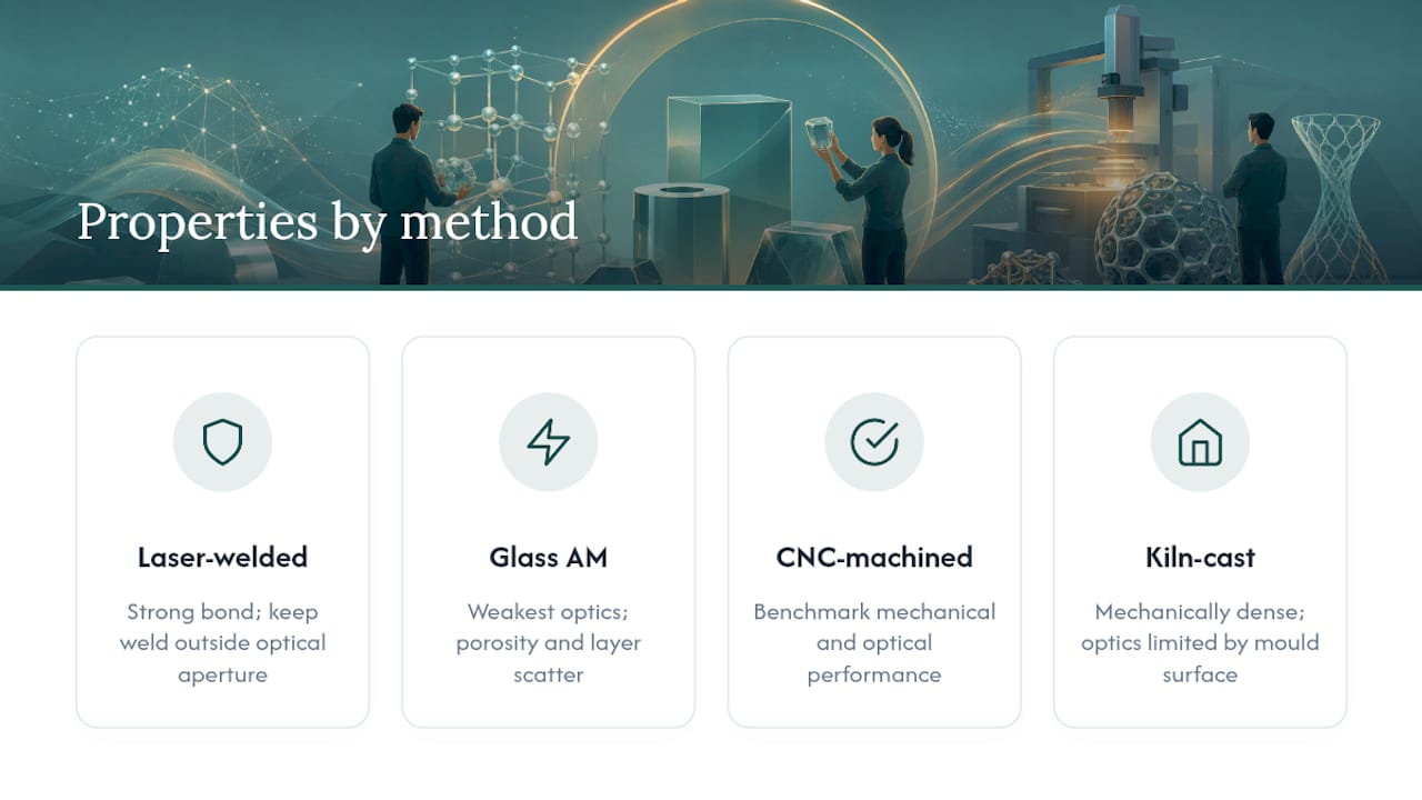
Laser-welded assemblies show strong bond integrity, holding multi-bar pressures in validated tests, because the weld fuses glass to glass at a molecular level rather than relying on an adhesive interface. Optically, laser-modified regions can introduce localised stress or scatter near the weld line, so parts destined for imaging or beam-path applications often need the weld kept outside the optical aperture.
Glass AM parts, whether from DIW, extrusion, or powder sintering, tend to show the weakest as-built optical clarity of any method here. Layer boundaries scatter light and internal porosity from incomplete sintering can leave micro-voids that weaken the part mechanically under load. Post-sintering density and a full anneal close most of this gap, but rarely close it completely, which is why LLNL’s own reporting on optical-quality glass printing frames current AM capability as a research-stage advance rather than a production-ready alternative to ground optics.
CNC-machined and polished parts remain the benchmark for both mechanical predictability and optical performance, since the base material is solid, unmodified glass throughout. Kiln-cast parts fall between the two: mechanically sound because the glass is fully dense, but optically limited by mould-surface quality unless cold-worked afterwards. A useful working rule: pick laser methods for sealed, pressure-bearing microstructures, AM for complex internal geometry where optical clarity is secondary, and machining wherever the part must perform optically as delivered.
What does rapid glass prototyping cost by method?
Cost tracks complexity and post-processing far more than raw material price, since glass itself is a small fraction of most prototype budgets. Laser micromachining carries low tooling cost because there is no mask or mould, but per-part cost climbs with feature density since the process is inherently serial; a single research chip with modest features can be inexpensive, while a part packed with fine internal channels takes proportionally longer on the laser and costs more.
Glass AM sits in a similar band for tooling cost, since no mould is needed either, but the sintering furnace cycle and subsequent finishing add a fixed cost regardless of part complexity. A simple printed blank costs less than a laser-written equivalent; a geometrically complex monolithic part with internal channels usually costs less in AM than it would to machine and bond from several pieces.
CNC machining carries the highest cost per hour of shop time but often the lowest total cost for simple geometries, because there is no sintering cycle or laser dwell time to pay for. Waterjet and kiln-casting sit at the lower end for simple shapes, since both processes work quickly on straightforward geometry, but casting adds cost fast once cold-working is needed to correct mould-surface texture.
Across every method, polishing to optical grade and any coating step add a cost layer that scales with area and specification tightness, frequently equalling or exceeding the fabrication cost itself for high-precision optics. Engineers requesting quotes should ask suppliers to separate fabrication, finishing, and inspection costs rather than accept a single bundled figure, since that breakdown is the only way to compare methods fairly. Precision Glasses can provide that breakdown through its technical glass and machining services.
How do you test a rapid prototyped glass part?
Verifying that a prototype actually does what it was designed to do needs a test plan matched to the part’s function, not a generic inspection checklist. Optical prototypes typically go through interferometry to check wavefront error and surface figure, plus transmission or reflectance measurement across the working wavelength band if a coating is involved.
Mechanical and pressure-critical parts, particularly sealed microfluidic or sensor housings, need leak and burst testing before they go anywhere near a live application. The laser-welded devices referenced earlier were pressure-tested to a documented threshold precisely because a weld that looks sound under a microscope can still fail under flow pressure. Thermal cycling tests matter wherever the part will see repeated heating and cooling, since residual stress from incomplete annealing tends to surface only after several cycles, not the first one.
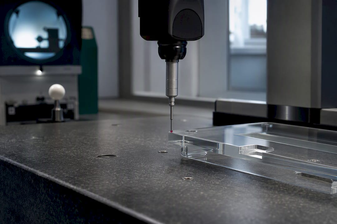
Dimensional verification runs through coordinate measuring machines or optical comparators for tight-tolerance features, cross-checked against the original CAD model rather than a printed drawing alone. A traceable metrology report, tied to the specific batch and material lot, is what separates a supplier’s informal quality check from a documented one that will survive an audit. Any application touching medical devices or regulated defence work should expect this traceability to align with ISO 9001 or ISO 13485 practice as a baseline, not an optional extra.
Author perspective: choosing prototypes that de-risk the project
Prototyping should validate the riskiest assumption in the design, not attempt to mimic the eventual production process. If the real unknown is whether a bonded channel holds pressure, test that first with the fastest method available, even if it is not the process you will scale with. Too many teams over-invest in prototype fidelity and under-invest in testing the one function that could sink the entire design.
— Alexandra
Ready to move from prototype to production glass parts?
Laser micromachining and glass AM answer the speed question, but neither replaces a manufacturing partner once a design needs to scale reliably. CNC glass machining, optical finishing, and coating application can be run under one traceable workflow, so a validated prototype moves into volume production without re-qualifying a new supplier from scratch.

Before reaching out, have your CAD file, critical tolerances, material grade, and target turnaround ready. That preparation alone cuts the feasibility conversation from days to a single call. Design-for-manufacture questions and pressure or optical requirements are reviewed as standard practice before any cutting begins, which catches conflicts while they are still cheap to fix. Visit the services page to submit a request for quote and start that feasibility review.
Primary sources and recommended further reading
- Maskless rapid manufacturing of glass microfluidic devices documents the laser welding pressure and temperature figures cited above in full experimental detail.
- MIT Lincoln Laboratory’s low-temperature glass AM research explains the thermal mechanics behind direct-ink-writing routes.
- LLNL’s report on optical-quality glass printing sets realistic expectations for where glass AM currently stands against ground optics.
- Edmund Optics’ rapid prototyping page gives real-world lead times for stock and custom optical components.
Sources
- Maskless rapid manufacturing of glass microfluidic devices — Krystian L. Wlodarczyk et al.
- Low-temperature additive manufacturing of glass — MIT Lincoln Laboratory
- 3D printing optical-quality glass — Lawrence Livermore National Laboratory (LLNL)
- Rapid prototyping capabilities — Edmund Optics
FAQ
What is rapid prototyping?
Rapid prototyping is any fabrication approach that produces a working part directly from a design file in days or weeks rather than the months a full production tooling cycle would take. In glass, that means laser micromachining, additive manufacturing, or fast-turn CNC machining instead of hard tooling and mould-based mass production.
Is there a 3D printer that can print glass?
Yes, several systems print glass through direct ink writing, molten extrusion, or powder sintering, though the part typically needs sintering, annealing, and polishing afterwards to approach usable optical clarity. Suppliers such as Glassomer offer this commercially for prototyping, while LLNL’s research shows optical-grade results remain largely at laboratory scale.
What are the different types of optical glass?
Fused silica offers the widest transmission range and lowest thermal expansion, making it common for demanding optics and harsh environments. Borosilicate and technical soda-lime grades cost less and machine more easily, and are suited to less extreme optical or mechanical specifications. Precision Glasses supplies optical components including achromatic and aspheric lenses across these material grades.
Can I 3D print onto glass?
Depositing conductive traces, coatings, or ceramic printing onto an existing glass surface is a separate process from printing the glass itself, and it is well established in industrial glass finishing. Embedding electronics or sensors during a glass AM build is possible but constrained by the sintering temperature the embedded component must survive.
How much does rapid glass prototyping cost?
Cost depends heavily on geometry complexity, feature density, and the finishing specification rather than raw material, so a simple laser-cut chip costs far less than a part needing full optical polish and coating. Precision Glasses provides pricing on request through its services page once tolerances and material grade are confirmed.


