
Precision glass in LiDAR is defined as optically engineered glass that transmits, directs, and protects laser signals across the full sensing cycle. Its function goes well beyond a protective cover. NIR transmissive glass covers achieve optical transmittance of 88% or greater across the 780–2,500 nm near-infrared range, which is the working band of most commercial and defence-grade LiDAR systems. Anti-reflective coatings, heat wire layers, and stress-compensating multilayer stacks each address a distinct failure mode. Engineers who treat the glass component as an afterthought routinely discover that it is the single element limiting system range, point-cloud accuracy, and all-weather reliability.
How does precision glass affect LiDAR sensor accuracy and range?
The optical properties of glass determine how much laser energy reaches the target and how cleanly the return signal is captured. Two variables matter most: transmittance and wavefront distortion. A glass component that absorbs or scatters even a small fraction of NIR energy reduces effective detection range in a non-linear way, because signal-to-noise ratio degrades faster than raw power loss suggests.
Anti-reflective coatings address the most direct source of energy loss. AR coatings on LiDAR glass improve transmittance by 2–3%, which translates directly into stronger return signals and more reliable point-cloud density at long range. That gain sounds modest, but at 200 m it can mean the difference between resolving a pedestrian and missing them entirely.

Precision mirrors demonstrate the range argument most clearly. High-precision optical mirrors increased LiDAR detection range by 13%, adding 2 km to sensing distance without any change to the laser source or electronics. The improvement came entirely from tighter surface figure tolerances and stress-compensating multilayer coatings that kept the mirror flat under thermal load.
Stress-compensating layers in multilayer optical coatings reduce wavefront distortion by counterbalancing the mechanical stress each deposited layer introduces. Without compensation, cumulative stress bends the substrate, misaligning the beam path and degrading angular resolution. This is a manufacturing detail that has direct system-level consequences.
Pro Tip: When specifying a LiDAR glass cover, request wavefront error data alongside transmittance figures. A component with 90% transmittance but poor surface figure will underperform a 88% transmittance component with tight flatness tolerances.
| Property | Engineering significance |
|---|---|
| NIR transmittance ≥88% | Maintains signal strength across the full 780–2,500 nm working band |
| AR coating gain (2–3%) | Reduces reflection loss, improving point-cloud density at range |
| Stress-compensated multilayer | Preserves surface figure under thermal cycling, protecting beam alignment |
| Surface flatness (wavefront error) | Controls angular resolution and false-positive rate in point-cloud data |
What causes optical signal distortion through glass in LiDAR?
Glass interfaces introduce three distinct distortion mechanisms: Fresnel reflection, thermal deformation, and geometric ghosting. Each degrades point-cloud data in a different way, and each requires a separate engineering response.
Fresnel reflection at an uncoated glass surface sends a fraction of the outgoing laser pulse back into the receiver. The receiver interprets this internal reflection as a return from a real object. The result is a “ghost” point at a fixed offset distance, which corrupts the point cloud with phantom geometry. Placing LiDAR behind windshields amplifies this problem because automotive glass has a curved surface and a laminated structure, both of which multiply reflection paths.
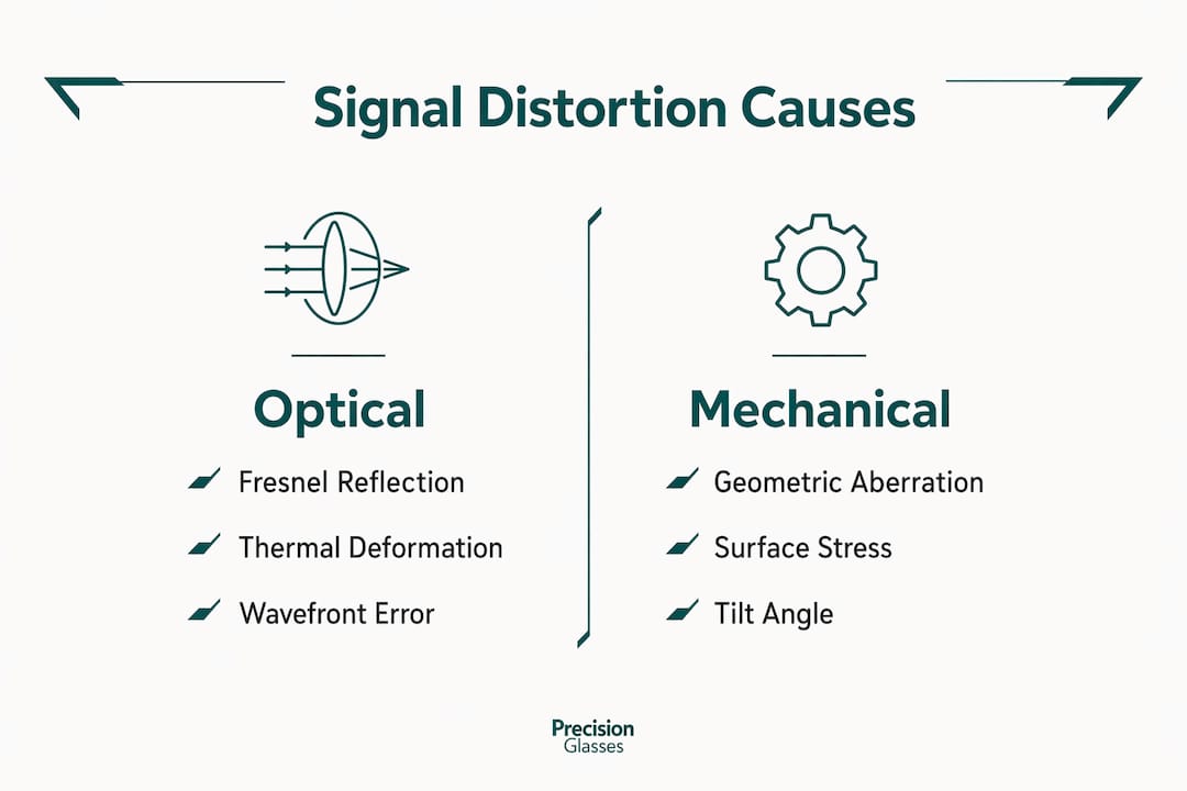
Thermal ageing changes the refractive index and surface geometry of glass over time. A cover that passes optical qualification at room temperature may drift out of specification after repeated thermal cycling between -40°C and +85°C. Validation against thermal ageing profiles is now standard practice for automotive LiDAR glass, using Fresnel equation modelling to predict performance at end-of-life rather than at initial installation.
Glass-induced reflection artefacts in terrestrial laser scanning are well documented. Novel descriptors that integrate geometric and semantic information, such as the RE-LGGS approach, can detect and remove these artefacts from point-cloud data in post-processing. That is a useful mitigation, but it is computationally expensive and introduces latency that real-time autonomous systems cannot tolerate.
The engineering priority is therefore to eliminate artefacts at source through glass design rather than correct them in software. The following approaches are established practice:
- Apply broadband AR coatings tuned to the specific laser wavelength (typically 905 nm or 1,550 nm) to suppress Fresnel reflections below the detection threshold.
- Use optical modelling, including Fresnel equation simulation, during the design phase to predict reflection paths before fabrication.
- Specify thermal ageing validation as a qualification requirement, not an optional test.
- Select glass with low birefringence to avoid polarisation-dependent signal variation.
- Design mounting geometry to tilt the glass cover slightly off-axis, directing any residual reflection away from the receiver aperture.
Pro Tip: A tilt angle of 3–5 degrees on the cover glass is often sufficient to redirect ghost reflections outside the receiver field of view. Confirm this with ray-trace modelling before committing to a mechanical design.
What materials and designs advance precision glass for LiDAR?
Material selection is the first design decision for any LiDAR glass component, and it is the decision with the longest downstream consequences. Standard borosilicate or fused silica covers suit most terrestrial applications. Extreme environments demand materials with fundamentally different spectral and mechanical properties.
Custom LiDAR optics for maritime defence use sapphire, zinc sulphide, and germanium, each chosen for its specific spectral transmission profile and mechanical resilience. Sapphire transmits from the ultraviolet through the mid-infrared and offers exceptional hardness, making it resistant to salt spray abrasion. Zinc sulphide covers the 1–12 µm band, which is relevant for thermal imaging LiDAR variants. Germanium is the material of choice for long-wave infrared applications where standard glass is opaque.
The trend towards custom precision optics is driven by requirements from maritime and defence sectors that face harsh environments with tailored spectral needs. Generic catalogue optics rarely meet the combined requirements of spectral transmission, mechanical ruggedness, and environmental sealing that mission-critical systems demand.
The table below compares generic catalogue glass against custom-engineered solutions across the criteria that matter most for LiDAR integration.
| Criterion | Generic catalogue glass | Custom-engineered glass |
|---|---|---|
| Spectral tuning | Fixed, broad-band | Matched to laser wavelength and detector band |
| AR coating | Standard single-layer | Multilayer, stress-compensated, wavelength-specific |
| Thermal performance | Unvalidated at extremes | Qualified to application temperature range |
| Heating element | Not available | Integrated heat wire for frost prevention |
| Mechanical fit | Standard dimensions | CNC-machined to system envelope |
| Qualification data | Datasheet only | Full test report including thermal ageing |
Heating elements integrated directly into the glass cover address a specific operational failure mode. Heat wire layers in LiDAR covers prevent frost and ice accumulation on the optical surface, maintaining transmittance in winter conditions. Both direct surface heating and indirect heating configurations are used, depending on the cover geometry and power budget available.
For engineers working on glass integration in ADAS systems, the heating element specification must account for the thermal gradient across the glass thickness. An uneven gradient introduces refractive index variation that degrades beam quality, so the wire pattern and power density require careful modelling alongside the optical design.
How is precision glass manufactured for LiDAR integration?
Manufacturing precision glass for LiDAR is a multi-stage process where each step either preserves or degrades the optical performance established in the design phase. The sequence matters as much as the individual operations.
- Substrate selection and inspection. The glass blank is inspected for inclusions, bubbles, and refractive index homogeneity before any machining begins. Defects in the bulk material cannot be corrected by surface finishing.
- CNC grinding and polishing. The blank is ground to near-net shape, then polished to the specified surface figure. For LiDAR covers, flatness tolerances are typically specified in fractions of a wavelength. Polishing removes the sub-surface damage layer left by grinding, which would otherwise scatter the laser beam.
- AR coating deposition. Multilayer AR coatings are deposited by physical vapour deposition or ion-beam sputtering. The coating recipe is tuned to the target wavelength. Stress-compensating layers are included in the stack to prevent substrate deformation after deposition.
- Heat wire integration. Where specified, resistive heating elements are bonded to or embedded within the glass assembly. The wire pattern is designed to distribute heat uniformly across the optical aperture without introducing optical obstruction.
- Bonding and sealing. Where the glass cover forms part of a sealed housing, adhesive bonding layers are applied and cured under controlled conditions. Bond line thickness and uniformity affect both mechanical strength and optical path length.
- Quality assurance. Each component is measured for transmittance, surface figure, and coating uniformity. Thermal cycling tests validate performance across the operating temperature range. Components that fall outside specification are rejected rather than reworked, because rework risks introducing contamination.
The precision glass manufacturing workflow at Precision Glasses follows this sequence with documented hold points at each stage. The approach ensures that optical and mechanical requirements are verified independently before the component is released for integration.
Cost considerations are real. Custom AR coatings and stress-compensating stacks add to unit cost, but the system-level return, measured in detection range, point-cloud quality, and reduced software correction overhead, consistently justifies the investment for high-performance LiDAR programmes.
Key takeaways
Precision glass is the primary determinant of LiDAR detection range, point-cloud accuracy, and all-weather reliability, and its specification must begin at the system design stage, not after the sensor is chosen.
| Point | Details |
|---|---|
| NIR transmittance sets the baseline | Glass covers must achieve ≥88% transmittance across 780–2,500 nm to preserve signal integrity. |
| AR coatings deliver measurable range gains | A 2–3% transmittance improvement from AR coatings translates directly into stronger returns at long range. |
| Ghost artefacts require design-level solutions | Fresnel reflections and thermal drift must be addressed through glass design, not post-processing alone. |
| Material choice drives environmental resilience | Sapphire, zinc sulphide, and germanium extend LiDAR capability into extreme spectral and environmental conditions. |
| Manufacturing sequence determines final performance | Each production step from polishing to thermal validation either preserves or compromises the optical specification. |
Precision glass in LiDAR: where the real engineering challenge sits
Working with engineers across defence, automotive, and industrial sensing programmes, I have noticed a consistent pattern. The glass component is specified last, often as a procurement line item rather than an optical design decision. That sequence is backwards, and it costs programmes time and money.
The optical path through the cover glass is not separable from the rest of the LiDAR system. The AR coating bandwidth must match the laser wavelength. The surface figure tolerance must be consistent with the beam divergence. The thermal performance must be validated against the deployment environment. None of these decisions can be made correctly after the sensor and housing are already fixed.
My practical advice: bring the glass specification into the system design review, not the component procurement review. Define transmittance, wavefront error, thermal range, and heating requirements alongside the laser and detector specifications. The glass component design process at Precision Glasses is structured to support exactly this kind of early-stage collaboration, and the programmes that engage at that point consistently achieve better first-article results.
The materials frontier is also moving quickly. Sapphire and zinc sulphide are established for defence applications, but new coating chemistries and bonding techniques are extending their use into automotive and industrial LiDAR at lower cost. Engineers who understand the material options now will be better placed to specify the next generation of sensors.
— Alexandra
Precision Glasses: technical glass for demanding LiDAR applications

Precision Glasses designs and fabricates technical glass components for LiDAR systems across automotive, defence, aerospace, and industrial sensing applications. Our components are specified to meet NIR transmittance requirements, thermal operating ranges, and surface figure tolerances defined by your system design, not by catalogue defaults. We supply AR-coated covers, precision mirrors, and heated glass assemblies with full qualification data. If your programme requires a custom optical solution with documented performance across temperature, contact Precision Glasses to discuss your specification. We also offer optical component engineering support for teams integrating glass into new LiDAR architectures.
FAQ
What is the role of precision glass in LiDAR?
Precision glass in LiDAR provides high-transmittance, optically flat coverings and components that protect the sensor, transmit the laser signal with minimal loss, and maintain alignment under thermal and mechanical stress. Its specification directly determines detection range and point-cloud accuracy.
What NIR transmittance should LiDAR glass achieve?
LiDAR glass covers should achieve transmittance of 88% or greater across the 780–2,500 nm near-infrared range. AR coatings add a further 2–3% improvement, which has measurable impact on signal strength at long range.
How do AR coatings reduce LiDAR signal distortion?
AR coatings suppress Fresnel reflections at the glass surface, reducing ghost artefacts in the point cloud and improving the energy delivered to and from the target. Coatings tuned to the specific laser wavelength, typically 905 nm or 1,550 nm, deliver the greatest benefit.
Why do LiDAR systems behind windshields need special glass treatment?
Automotive windshields introduce multiple reflection paths and thermal drift that corrupt point-cloud data with phantom geometry. Predictive modelling using Fresnel equations and thermal ageing validation is required to qualify glass covers for behind-windshield LiDAR integration.
What materials are used for LiDAR glass in extreme environments?
Sapphire, zinc sulphide, and germanium are the principal materials for LiDAR optics in maritime defence and other extreme environments. Each offers a distinct spectral transmission profile and mechanical resilience suited to specific wavelength bands and environmental conditions.


