
Optical clarity is one of the most misunderstood properties in precision materials specification. Many engineers and procurement managers assume that if a material transmits light well, it is optically clear. That assumption leads to costly failures in defence sensor windows, medical endoscope lenses, and automotive head-up display glazing. Understanding what is optical clarity in precise, measurable terms means going well beyond simple light transmission. It requires understanding haze, surface finish, angular performance, and how each of these parameters shifts with material thickness and manufacturing method.
Table of Contents
- Defining optical clarity and its measurement
- Factors affecting optical clarity in industrial glass and plastics
- Advances in optical clarity for micro 3D printing and high-precision applications
- Industry standards and quality control for optical clarity in precision applications
- Practical tips for specifying and procuring high-clarity optical materials
- Optical clarity: overlooked nuances that shape real-world performance
- Explore precision glass solutions for your optical clarity needs
- Frequently asked questions
Key Takeaways
| Point | Details |
|---|---|
| Optical clarity measures | Optical clarity involves both how much light passes through a material and how little it scatters to maintain sharpness and visibility. |
| Haze affects clarity | Haze quantifies scattered light causing cloudiness; even low haze percentages are crucial for aerospace and medical optics. |
| Surface quality matters | Micron-scale surface roughness and scratches create light scattering that diminishes optical performance. |
| Standards guide quality | ASTM D1003 and EN 379 standards provide key frameworks for measuring and classifying optical clarity in industry. |
| Procurement tips | Specify haze, thickness, angular dependence, and surface quality, and require certified test data when sourcing optical materials. |
Defining optical clarity and its measurement
Optical clarity is characterised by two primary parameters: total luminous transmittance and haze. Transmittance measures the percentage of light that passes through a material. Haze measures the fraction of that transmitted light that scatters more than 2.5 degrees from the incident beam, which is what causes that milky, diffuse appearance in otherwise transparent materials. A material can transmit 92% of incident light and still appear foggy if its haze value is above 5%.
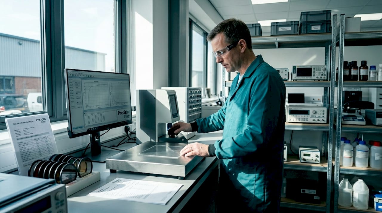
The industry-standard method for quantifying both parameters is ASTM D1003, which uses a haze meter equipped with an integrating sphere to capture total and diffuse transmitted light. For most precision optics applications, haze values below 1% are required. For demanding applications in medical imaging or aerospace sensor systems, haze targets of 0.3% or lower are not uncommon.
It is worth separating clarity from transparency as concepts. Transparency simply confirms that light passes through a material. Optical clarity, by contrast, describes the quality of that transmission. You can think of it this way: frosted glass is transparent but not optically clear. Clean borosilicate glass with a polished surface is both. When reviewing advanced glass specifications, you will notice that the most demanding applications always specify haze and transmittance together rather than relying on one figure alone.
| Parameter | What it measures | Acceptable threshold (precision optics) |
|---|---|---|
| Luminous transmittance | Total light passing through | Above 92% |
| Haze | Scattered light fraction | Below 1% (often below 0.3%) |
| Clarity | Wide-angle scattered light | Rated separately from haze |
| Refractive index uniformity | Internal homogeneity | Varies by application |
Key parameters to specify for optical clarity:
- Total luminous transmittance: measured as a percentage; must be specified at application thickness
- Haze percentage: the critical indicator of image crispness, not just light volume
- Optical clarity rating: complements haze by quantifying large-angle scattering
- Surface flatness and finish: directly influences haze in finished components
Factors affecting optical clarity in industrial glass and plastics
Surface quality is perhaps the single greatest driver of optical clarity outcomes in manufactured components. Scratches and roughness cause light scattering that reduces contrast and resolution, even in materials with excellent bulk transmittance. A surface with root mean square roughness above a few nanometres can introduce measurable haze, which is why polishing processes and scratch-dig specifications (such as 20-10 or 10-5) are mandatory in aerospace and medical optical procurement.
Material thickness is another variable that procurement teams frequently underestimate. Acrylic optical sheets tested per ASTM D1003 show a measurable decrease in clarity as thickness increases, because internal scattering centres accumulate over a longer optical path. If your haze specification was validated on a 3mm sample but the final application uses 6mm, you may be qualifying a material that will fail in service.
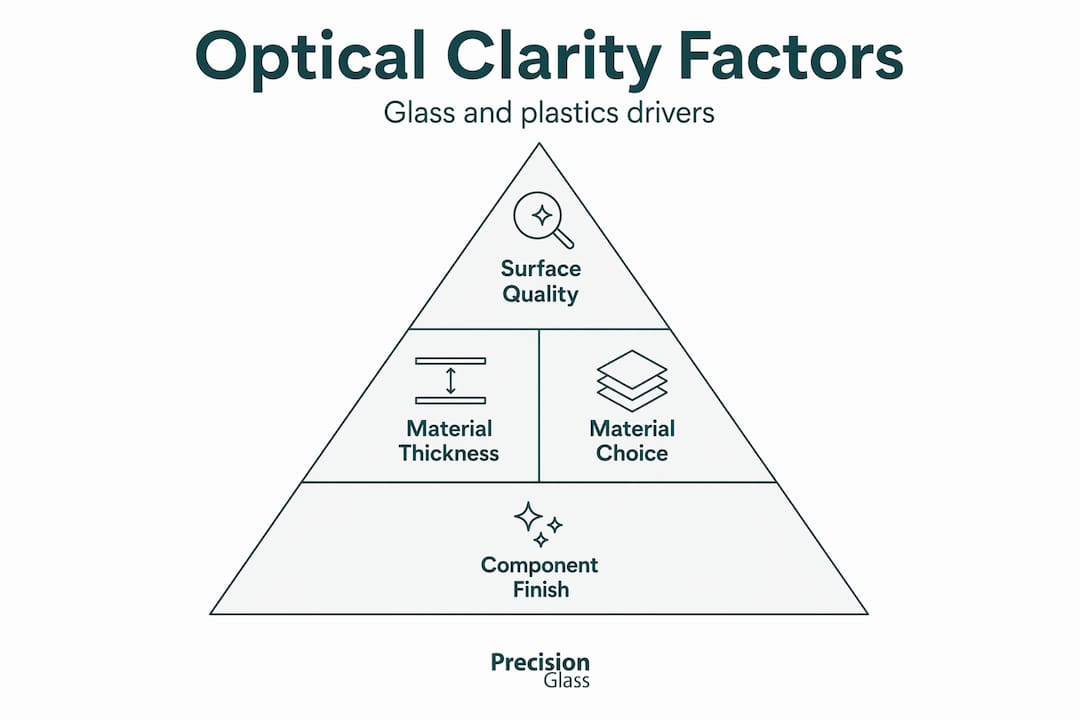
Material choice itself sets the baseline. High-quality optical glass typically achieves haze values below 0.1% when polished correctly. Acrylic, whilst lighter and easier to machine, tends toward haze values of 0.5% to 2% depending on grade and thickness. Polycarbonate offers impact resistance but often carries higher inherent haze, making it less suitable for applications where image fidelity is paramount.
Manufacturing process control is equally important. Annealing schedules, grinding depth, and polishing sequences all affect the density of sub-surface damage and residual surface roughness. For display glass performance in automotive dashboards, for example, even minor polishing inconsistencies translate directly into visible image artefacts under bright ambient conditions.
Key factors affecting optical clarity:
- Surface finish and scratch-dig specification
- Material homogeneity and internal bubble or inclusion count
- Component thickness relative to qualification thickness
- Annealing and thermal treatment quality
- Coating adhesion and uniformity when anti-reflection or protective coatings are applied
Pro Tip: Always request haze measurements taken at the actual finished component thickness, not on raw material stock. The difference can be significant, particularly for glass above 4mm or acrylic above 5mm.
Advances in optical clarity for micro 3D printing and high-precision applications
One of the more compelling recent developments in optical clarity is the resolution of longstanding transparency problems in micro 3D printed components. For years, printed optics suffered from inherent surface roughness at the layer interface, scattering light and making true optical clarity almost impossible to achieve at small scales. This limited their use in sensors, microfluidic devices, and miniaturised imaging systems.
BMF (Boston Micro Fabrication) has addressed this directly. Their Clear resin, used with Projection Micro Stereolithography (PµSL) technology, achieves over 90% light transmittance at layer heights of 10 to 50 micrometres. This is a step change in capability. The resolution is fine enough that surface roughness at micron scales no longer causes the scattering that previously made 3D printed optics optically unreliable.
“Achieving true optical transparency in 3D printed components at micron-scale accuracy opens pathways for sensors, microfluidic chips, and miniaturised optics that previously required conventional grinding and polishing.” — 3D Printing Industry, 2024
For engineers working on glass component design in electronics or medical devices, this matters because it expands what is achievable in complex geometries. Features that once required multi-step machining can now be produced as single printed components with verified optical clarity. The critical enabling factors include layer height control, resin formulation, and injection speed parameters during printing.
Key advances enabling optical clarity in precision micro manufacturing:
- PµSL technology achieving 2 to 10 micrometre resolution
- Clear resin formulations with transmittance above 90%
- Reduced layer roughness eliminating primary scattering mechanism
- Compatibility with microfluidic and sensor integration requirements
Industry standards and quality control for optical clarity in precision applications
Understanding measurement is one thing. Knowing which standards govern acceptance in your sector is what allows you to write procurement specifications that hold up under scrutiny. EN 379 rates optical clarity on a 1 to 3 scale, with Class 1 being the highest clarity, and is widely referenced for defence visors, protective optics, and aerospace face shields. A Class 1 rating demands minimal angular distortion and colour imbalance, making it the appropriate requirement for any application where the operator’s situational awareness depends on visual fidelity.
For materials qualification, ASTM D1003 and ISO 14782 are the dominant measurement standards. Even a 0.1% variation in haze can trigger qualification failure in aerospace programmes, which underlines why calibration documentation matters as much as the test result itself.
Practical quality control checklist for optical glass procurement:
- Specify haze and transmittance targets with the material thickness explicitly stated
- Include scratch-dig and surface flatness (typically λ/10 or better for precision use)
- Reference the applicable standard (ASTM D1003, ISO 14782, or EN 379)
- Require certified calibration records for all measurement equipment used
- Request angular dependence and colour shift data for components used at oblique angles
- Specify acceptance criteria for inclusions, bubbles, and internal striae
| Sector | Primary clarity standard | Typical haze requirement |
|---|---|---|
| Aerospace | ASTM D1003 / ISO 14782 | Below 0.3% |
| Medical devices | ISO 10110 / ASTM D1003 | Below 0.5% |
| Defence optics | EN 379 Class 1 | Class 1 distortion rating |
| Automotive glazing | ASTM D1003 | Below 1% |
| Electronics displays | ASTM D1003 | 0.5% to 1% |
Pro Tip: When reviewing quality assurance processes at a potential supplier, ask specifically whether their haze meter is calibrated against NIST-traceable reference standards. Uncalibrated equipment is one of the leading sources of out-of-spec deliveries in precision optical glass procurement.
Practical tips for specifying and procuring high-clarity optical materials
Specifications that look complete on paper can still miss critical performance requirements. Thickness-dependent haze increase and angular dependence are two of the most frequently overlooked variables, and both lead to downstream qualification failures that could have been caught at the procurement stage.
For demanding applications such as medical endoscopes or automotive head-up displays, combining haze below 1% with surface flatness of λ/10 and a scratch-dig of 20-10 is the minimum baseline. Specifying one parameter without the others leaves gaps that suppliers may exploit, not necessarily through poor intent, but simply because an incomplete specification gives insufficient guidance.
When working with optical component specifications, always include the following in your procurement documentation:
- Haze and transmittance values at the finished component thickness
- Surface quality specification (scratch-dig rating and surface roughness Ra)
- Angular dependence requirements if the component will be viewed at angles beyond 15 degrees
- Environmental stability requirements (thermal cycling range, humidity exposure)
- Coating specifications if anti-reflection or hard coatings are applied
- Certified test reports referencing ASTM D1003 or the applicable equivalent
Allow time in your programme for prototyping and validation with polished production-representative samples before committing to volume orders. Material qualification on catalogue samples is rarely sufficient for defence or medical programmes.
Pro Tip: For components used in imaging or detection systems, supplement haze meter data with interferometric testing. Interferometry reveals wavefront errors and surface irregularities that haze measurements miss entirely, particularly in thicker glass elements.
Optical clarity: overlooked nuances that shape real-world performance
We have observed a consistent pattern across procurement programmes in defence, aerospace, and medical device sectors. Engineers specify haze and transmittance carefully, receive compliant test certificates, and then encounter performance issues in integration testing. The reason is almost always the same. Standard haze and transmittance metrics tell you how much light passes through and how much scatters, but they do not tell you how the material behaves at the specific angles, wavelengths, and thermal conditions of your actual application.
Angular dependence and interferometry tests are the tools that surface these hidden problems. A lens element may test at 0.4% haze in normal incidence and introduce unacceptable wavefront distortion at 30 degrees. An automotive glazing panel may meet every haze specification and still create ghost images in a head-up display because its flatness is λ/4 rather than λ/10.
The uncomfortable truth is that optical clarity is a composite property. Surface finish, internal material homogeneity, angular spectral behaviour, and long-term material stability all contribute. When any one of these is assessed in isolation, you are measuring a component of clarity, not clarity itself. We would encourage procurement managers to treat optical testing insights as a programme investment rather than an administrative step. The cost of thorough pre-qualification testing is a fraction of the cost of a failed system integration.
The suppliers who understand this approach the problem differently. They do not hand you a haze certificate and close the conversation. They discuss your end-use conditions, suggest complementary tests, and flag material thickness or coating interactions before they become field failures. That depth of engagement is what separates a qualified optical glass partner from a commodity supplier.
Explore precision glass solutions for your optical clarity needs
At Precision Glasses, we engineer and supply custom glass components built to meet the most demanding optical clarity specifications across defence, aerospace, medical devices, and automotive sectors. Every component we produce is backed by meticulous quality assurance processes, certified measurement documentation, and close collaboration with your engineering team from design through to delivery.
Our technical glass products are engineered to specified haze, transmittance, surface flatness, and scratch-dig requirements. We support your programme from initial design through to full production, with our glass component design guide helping your team translate application requirements into manufacturable specifications. If you are procuring optical components for a critical application, contact our team to discuss how we can deliver verified optical clarity performance your programme depends on.
Frequently asked questions
What exactly is optical clarity in materials?
Optical clarity refers to how well light passes through a material with minimal scattering, allowing crisp, undistorted visualisation rather than the hazy appearance caused by diffuse light scatter.
How do haze and transmittance differ and affect clarity?
Transmittance measures the total light passing through a material, whilst haze quantifies the portion of that light that scatters and causes cloudiness; low haze with high transmittance together define optimal optical clarity.
Why is surface quality important for optical clarity?
Surface imperfections scatter incident light, reducing contrast and resolution in the transmitted image; scratches and surface roughness are primary causes of clarity degradation in high-precision optical systems.
What standards are used for measuring optical clarity in industry?
ASTM D1003 is the primary standard for haze and luminous transmittance measurement, whilst EN 379 classifies clarity for welding and protective optics in defence and aerospace applications.
How can procurement managers ensure materials meet optical clarity requirements?
Specify haze and transmittance at the actual finished component thickness, include surface quality and angular dependence parameters, and require certified ASTM D1003 test reports as part of your acceptance documentation.
Recommended
- How to design optical glass: expert steps for precision results – Precision Glass
- Optical coatings explained: technology, testing, and insights – Precision Glass
- Optical vs protective glass: key differences for industry – Precision Glass
- Achieve precision with advanced optical glass coating technology – Precision Glass