Optical glass coatings are no longer a secondary consideration in high-performance systems. Every engineer and procurement specialist working across aerospace, defence, medical devices, automotive, lighting, and electronics knows that coating failure can compromise an entire assembly. Performance benchmarks are rising sharply, environmental stress is more demanding than ever, and the window for acceptable error is narrowing. This guide works through the core technologies, preparation protocols, deposition methods, and verification standards that define world-class optical glass coatings in 2026, giving you the practical framework to specify, apply, and validate coatings that perform under real conditions.
Table of Contents
- Understanding optical glass coatings and industry drivers
- Preparation and prerequisites for optical glass coating
- Step-by-step: Applying advanced optical glass coatings
- Verification: Testing durability, optical performance, and troubleshooting
- What most guides miss: Nuances that define world-class optical coatings
- Precision glass solutions for your next project
- Frequently asked questions
Key Takeaways
| Point | Details |
|---|---|
| Know your standards | Always reference MIL-STD-810 or MIL-C-48497A for coating durability in advanced industries. |
| Match substrate and coating | Properly match substrate and coating materials to avoid thermal cycling failures and maximise endurance. |
| Choose advanced deposition | Hybrid ALD/sputtering techniques offer superior durability and performance in automotive and electronics. |
| Verify with correct tests | Test coatings using industry pulse-width LIDT and environmental methods to ensure compliance. |
| Monitor stress and quality | Ongoing monitoring and troubleshooting lead to longer-lasting, more reliable optical coatings. |
Understanding optical glass coatings and industry drivers
Optical glass coatings serve three primary functions: antireflection, spectral filtering, and surface protection. Each function is critical in its own right, and many modern applications demand all three simultaneously. An infrared camera lens in a defence platform must transmit maximum energy in a specific waveband, resist abrasion from field exposure, and survive thermal cycling from desert heat to arctic cold. A medical imaging objective must pass precise wavelengths with minimal scattering while resisting chemical cleaning agents. These are not theoretical demands. They are daily engineering realities.
Industry demand shapes coating development directly. Aerospace programmes push coatings into vacuum ultraviolet (VUV) territory, where traditional aluminium mirrors fall short. Defence applications require resistance to laser energy, sand, salt, and wide temperature swings. Medical device manufacturers need coatings that are biocompatible, optically pure, and reproducible at volume. Automotive heads-up display glass must maintain transmission and durability under vibration, UV exposure, and wide temperature ranges. Lighting and electronics applications demand consistent spectral performance across millions of units. Understanding the optical coatings explained principles behind each function is the first step towards specifying a coating that genuinely performs.
The performance benchmarks being achieved today illustrate how far the technology has advanced. LWIR AR coatings on chalcogenide materials now exceed 94% average transmittance, while reactively sputtered PVD aluminium mirrors achieve over 95% reflectance at 121.6 nm. These figures represent the current frontier and set the standard against which your coating choices should be measured.
| Coating type | Application | Performance benchmark |
|---|---|---|
| LWIR AR on chalcogenide | Thermal imaging, defence | >94% average transmittance |
| rPVD aluminium mirror | Aerospace, VUV systems | >95% reflectance at 121.6 nm |
| Hafnia-alumina mirror | High-power laser, defence | 20% higher LIDT vs hafnia-silica |
| Hybrid ALD/sputtering | Electronics, automotive | Conformal, durable layers |
Key technical drivers in optical coating selection include:
- Environmental resistance: resistance to salt fog, humidity, thermal shock, and UV exposure
- Laser performance: laser damage threshold (LIDT) tuned to operational pulse widths
- Transmission efficiency: maximising energy throughput within specific spectral bands
- Layer conformity: uniform coating thickness across curved and complex substrates
- Long-term stability: resistance to delamination and refractive index drift over service life
Understanding the role of glass in optical systems within your specific platform will sharpen your coating brief and reduce expensive specification errors downstream.
Preparation and prerequisites for optical glass coating
Preparation accounts for more coating failures than any deposition error. Engineers who invest in meticulous preparation consistently achieve better adhesion, lower defect rates, and longer coating lifetimes. This is not a suggestion. It is a verified pattern across high-reliability industries.
The first critical parameter is the coefficient of thermal expansion (CTE) match between the substrate and the coating. When a coated optic cycles between temperatures, mismatched CTEs generate interfacial stress. Over time, this stress causes delamination, microcracking, or catastrophic failure. Fused silica, BK7, and chalcogenide substrates all have distinct CTEs, and each requires a compatible coating material. Reviewing your glass specification guide early in the design phase will identify potential CTE conflicts before they become fabrication problems.
Durability standards for optical coatings are clearly defined. MIL-STD-810 and MIL-C-48497A set the benchmark testing regime, covering salt fog exposure, humidity cycling, thermal shock, abrasion resistance, and adhesion tests. For defence and aerospace applications, laser damage threshold testing is also mandatory. These standards are not optional compliance exercises. They are the contractual baseline for most government and prime contractor procurement.
| Preparation step | Requirement | Standard/method |
|---|---|---|
| Surface cleanliness | Particle-free, contamination-free | ISO 10110 cleanliness grades |
| CTE compatibility | Substrate and coating within tolerance | Material datasheet comparison |
| Temperature control | Deposition chamber at specified range | Process specification |
| Humidity control | Controlled environment pre-deposition | ISO 14644 cleanroom classes |
| Substrate inspection | No subsurface damage or scratches | interferometric surface testing |
Essential preparation steps before deposition include:
- Thorough cleaning using ultrasonic baths, solvents, and ion beam cleaning to remove contaminants
- Thermal pre-conditioning of substrates to stabilise CTE behaviour before coating
- Surface roughness measurement to confirm the substrate meets Ra specifications
- Environmental testing of substrate materials against anticipated service conditions
- Selection of coating material stacks compatible with both optical and mechanical requirements
Understanding the distinction between optical vs protective glass requirements will also guide your material selection, particularly when a single component must satisfy both optical transmission and mechanical durability criteria.
Pro Tip: Always request a CTE data sheet from your substrate supplier and cross-reference it against the thermal expansion behaviour of your proposed coating stack. A mismatch of even a few parts per million per degree Celsius can produce measurable stress at operational temperatures.
When designing optical glass components for high-reliability applications, building durability testing requirements into the design specification from the outset avoids costly redesign cycles later in the programme.
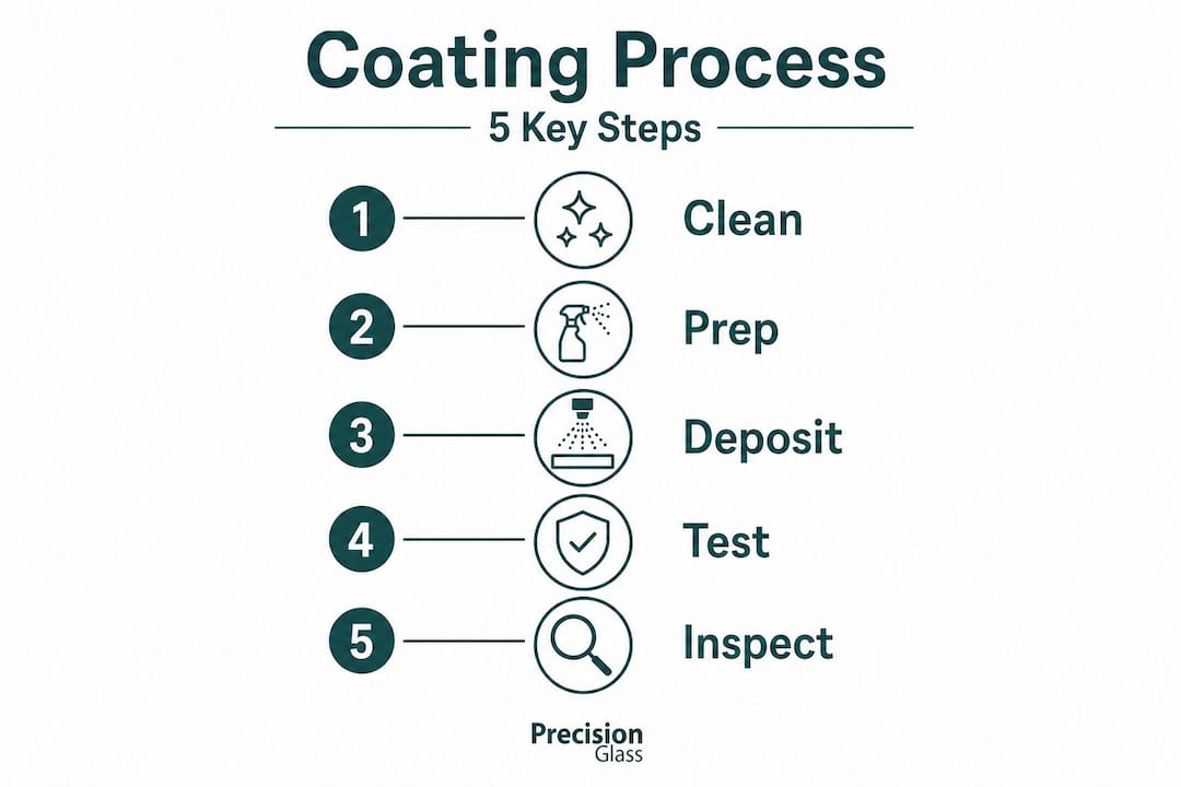
Step-by-step: Applying advanced optical glass coatings
With preparation complete and materials selected, the deposition process itself requires careful control at every stage. The following steps reflect current best practice for engineering-grade optical coatings across defence, aerospace, medical, and industrial applications.
Final surface preparation: Perform a final ion beam clean immediately before loading into the deposition chamber. This removes residual hydrocarbons and oxide layers that would compromise adhesion.
Chamber conditioning: Bring the deposition chamber to operating pressure and temperature. For reactive sputtering, stabilise gas flows before commencing deposition. Chamber walls should be pre-coated to reduce cross-contamination.
Substrate heating: Heat substrates to the specified pre-deposition temperature. This activates the surface and improves film nucleation. For chalcogenide substrates, temperature management is especially critical given their lower transition temperatures.
Deposition process selection: Choose between atomic layer deposition (ALD), physical vapour deposition (PVD) sputtering, or a hybrid ALD/sputtering approach. ALD/sputtering hybrids provide highly conformal, durable coatings particularly suited to the complex geometries common in automotive sensors and electronics packaging.
Layer-by-layer monitoring: Use in-situ optical monitoring to verify each layer’s optical thickness in real time. Deviations at early layers compound into significant spectral errors by the final stack.
Stress monitoring via Raman and EPR: Continuously monitor residual stress using Raman spectroscopy or electron paramagnetic resonance (EPR) techniques. High residual stress is a leading indicator of delamination risk. Catching stress build-up during deposition allows real-time process adjustment before failure occurs.
Pulse width control for LIDT: For defence and high-power laser applications, control the deposition process parameters to optimise the laser damage threshold. LIDT performance is pulse-width-dependent, meaning coatings optimised for nanosecond pulses will not necessarily perform at picosecond durations.
Post-deposition annealing: Where the process specification permits, apply controlled annealing to relieve residual stress and stabilise the refractive indices of deposited layers.
“Hybrid ALD/sputtering processes are transforming conformal coating capability for curved and complex substrates in automotive and electronics applications, where traditional line-of-sight deposition methods produce unacceptable thickness variation.”
Understanding the broader context of glass fabrication processes will help you align deposition choices with upstream fabrication constraints, particularly when working with polished curved surfaces or thin substrates.
Pro Tip: When specifying coatings for electronics packaging or automotive sensor covers, always request conformality data across the actual substrate geometry, not just flat witness samples. Thickness uniformity on a curved surface differs significantly from flat-sample measurements.
For teams procuring coatings for glass in electronics applications, confirming conformality requirements in the procurement specification prevents post-delivery disputes and rework costs.
Verification: Testing durability, optical performance, and troubleshooting
Applying a coating correctly is only half the task. Verification confirms that what was deposited will survive and perform throughout the operational service life. A robust verification programme covers both optical performance and environmental durability, using standardised protocols that procurement and engineering teams can directly reference in contracts.
Standard durability tests applicable to optical glass coatings include:
- Salt fog exposure: typically 48 to 96 hours at 5% NaCl solution, 35°C, to assess corrosion resistance
- Humidity cycling: 95% relative humidity at elevated temperatures to identify moisture-driven delamination
- Thermal shock: rapid cycling between temperature extremes to expose CTE-related stress failures
- Abrasion resistance: standardised cheesecloth or eraser abrasion tests to assess surface hardness
- Adhesion tape test: cross-hatch tape test to verify film adhesion to substrate at the interface level
Laser damage threshold verification deserves specific attention in defence and aerospace applications. Hafnia-alumina mirrors demonstrate a 20% higher picosecond LIDT compared with hafnia-silica mirrors, a difference that matters critically in high-energy pulsed laser systems. Selecting the wrong mirror coating for a pulsed laser application is not a marginal performance issue. It is a reliability and safety concern.
“Laser damage threshold results are only meaningful when tests are conducted at the pulse width and repetition rate that match the operational system. A coating qualified at nanosecond durations cannot be assumed safe at picosecond durations.”
Common coating failure modes and their root causes include:
- Adhesion failures: caused by surface contamination, insufficient ion beam cleaning, or CTE mismatch
- Delamination under thermal cycling: caused by residual stress accumulated during deposition
- Spectral shift after deployment: caused by moisture ingress into porous coating microstructures
- LIDT failure below specification: caused by nodular defects, contamination, or suboptimal process parameters
- Coating haze: caused by particulate contamination during deposition or inadequate chamber cleanliness
Troubleshooting these failures requires systematic root-cause analysis. For adhesion failures, start with the cleaning protocol and substrate surface roughness data. For LIDT failures, review the deposition process parameters and defect density mapping. For spectral shifts in the field, assess coating porosity using spectrophotometric drift data from accelerated ageing tests. Revisiting glass engineering basics often reveals substrate-level factors that the coating process cannot compensate for.
Interpreting test results requires matching outcomes against your specific industry requirement, not a generic pass/fail criterion. MIL-C-48497A adhesion requirements differ from the abrasion standards used in commercial medical device qualification. Know your specification before you interpret your results.
What most guides miss: Nuances that define world-class optical coatings
Most guides on optical glass coatings cover the sequence of deposition, the names of testing standards, and a list of common failure modes. What they rarely address is the engineering judgement required to avoid the failures that happen precisely because everything appeared to follow the correct procedure.
In our experience, the majority of preventable coating failures originate from two sources. The first is underestimating CTE mismatch. Engineers often check material datasheets at room temperature and assume compatibility. Real operating environments cycle through temperature ranges where CTE behaviour shifts non-linearly. Testing LIDT at operational pulse widths is similarly non-negotiable for defence applications, because damage mechanisms shift fundamentally between 0.3 and 8 picoseconds. A coating that passes nanosecond testing is not validated for a picosecond system.
The second source is the growing mismatch between legacy qualification test methods and new application demands. Hybrid ALD/sputtering has moved from research laboratories into volume production for automotive and electronics coatings, but many procurement specifications still reference PVD-only requirements. This creates situations where technically superior coatings fail paper qualification while inferior coatings pass. Updating your specification to reflect hybrid process capabilities is an active engineering task, not an administrative one.
Stress monitoring during deposition is another area where most guides offer only a sentence rather than a strategy. Real-time Raman and EPR monitoring during sputtering allows process engineers to detect stress accumulation before it reaches a threshold that will cause post-deposition delamination. Teams that implement continuous stress monitoring routinely achieve lower defect rates and better long-term coating stability than those who rely solely on post-deposition inspection.
We also strongly recommend aligning your coating specification with emerging glass technologies being qualified in aerospace and medical applications. The material stacks and process parameters being validated today will define the performance standards your competitors will be procuring against in three to five years.
Precision glass solutions for your next project
The detail in this guide reflects the level of engineering rigour we apply to every project at Precision Glasses. Our clients across defence, aerospace, medical, automotive, lighting, and electronics trust us because we understand that coating performance is a system-level outcome, not an isolated process step.
If you are specifying, sourcing, or evaluating optical glass coatings for a demanding application, our team can support you from initial design through fabrication and quality assurance. Explore our range of technical glass products and optical components tailored to your industry’s requirements. Our glass specification guide is a practical resource for procurement teams who need to translate performance requirements into precise, contractual specifications. Contact Precision Glasses to discuss your coating project with our engineering team.
Frequently asked questions
What is the highest durability standard for optical glass coatings?
MIL-STD-810 and MIL-C-48497A define the top durability benchmarks for optical coatings, covering salt fog, humidity, thermal shock, abrasion, and adhesion tests. These are the primary standards referenced in defence and aerospace procurement contracts.
Which coating process yields the best performance for electronics and automotive applications?
Hybrid ALD/sputtering methods provide highly conformal and durable coatings, making them the preferred choice for complex geometries common in electronics and automotive sensor applications. Stress monitoring via Raman or EPR during deposition further improves consistency.
How is laser damage threshold (LIDT) tested for defence applications?
LIDT must be tested at the operational pulse width, as damage mechanisms shift across durations from 0.3 to 8 picoseconds. Qualifying a coating at one pulse duration does not validate performance at another.
What optical transmission rates are considered best-in-class for antireflection coatings?
LWIR AR coatings on chalcogenide materials achieve over 94% average transmittance, while rPVD aluminium mirrors reach over 95% reflectance at 121.6 nm, representing the current industry frontier.
What can cause coating failures and how should they be addressed?
Coating failures most commonly result from substrate contamination, CTE mismatch, or inadequate durability testing protocols. Addressing failures requires systematic root-cause analysis beginning with preparation records and surface characterisation data.
Recommended
- Optical coatings explained: technology, testing, and insights – Precision Glass
- The vital role of glass in advanced optical systems – Precision Glass
- How to design optical glass: expert steps for precision results – Precision Glass
- Glass fabrication: Precision processes for critical industries – Precision Glass