
Glass machining is far more technically demanding than most engineers first assume. A proper explanation of glass machining goes well beyond scribing and snapping a pane. It encompasses precision grinding, CNC edging, laser ablation, and atomic-level surface finishing, each governed by strict material science constraints. In aerospace, medical devices, and semiconductor manufacturing, a single micro-crack or sub-surface defect can render a component unfit for purpose. Understanding the full range of glass machining processes, how they work, and where each technique applies is therefore fundamental for anyone specifying or procuring precision glass components.
Table of Contents
- Key takeaways
- Fundamental properties that shape glass machining
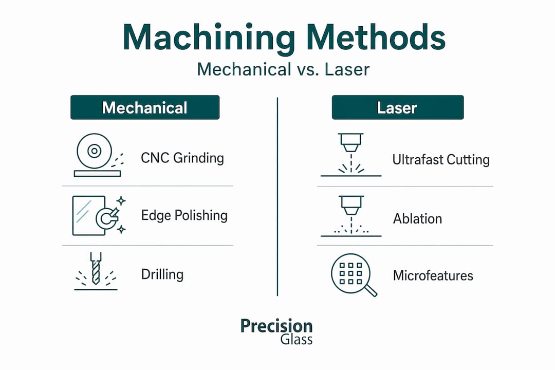
- Mechanical machining: CNC edging, grinding, and curve generation
- Laser-based glass machining: ultrafast cutting and ablation
- Hybrid and finishing processes: MRF, laser polishing, and inspection
- Process selection: applications, tolerances, and design alignment
- My perspective on where glass machining is heading
- Precision glass machining with Glassprecision
- FAQ
Key takeaways
| Point | Details |
|---|---|
| Brittleness governs everything | Glass type and fracture behaviour determine which machining process is appropriate before any toolpath is designed. |
| Mechanical and laser methods are complementary | CNC grinding and laser cutting solve different problems; the best outcomes come from selecting or combining them deliberately. |
| Micro-fracture control outranks dimension accuracy | Component strength depends more on sub-surface damage management than on achieving a nominal measurement. |
| Finishing is not optional | Magnetorheological finishing and laser polishing are production-critical steps in medical and semiconductor components, not cosmetic improvements. |
| Process selection drives quality | Glass type, geometry, volume, and tolerance must all feed the process decision before fabrication begins. |
Fundamental properties that shape glass machining
Glass is not a conventional engineering material. It is an amorphous solid with no slip planes, which means it cannot deform plastically before it fractures. Any engineer moving from metal to glass machining needs to internalise this difference immediately.
The core challenges break down as follows:
- Brittleness and chipping. Because glass fractures without yielding, even small localised stresses cause micro-cracks and edge chips. Managing crack propagation is the central problem in every glass machining process.
- Thermal sensitivity. Glass has low thermal conductivity, so heat generated during machining concentrates at the contact zone. Uncontrolled thermal gradients cause internal stress and subsurface fractures, often invisible until load testing.
- Sub-surface damage. Grinding leaves a damaged layer beneath the visible surface. Sub-surface damage directly impairs light transmission in optics and creates contamination pathways in semiconductor components. It must be removed by subsequent polishing stages.
- Material-specific behaviour. Borosilicate glass, fused silica, and aluminosilicate each respond differently to tool contact and thermal load. Fused silica, for instance, has very low thermal expansion but extreme hardness, requiring specific diamond tooling grades and lower feed rates.
The glass engineering fundamentals that govern these properties are not incidental. They are the starting point for every process decision. Micro-fracture management is more critical than nominal dimensional accuracy, because micro-cracks determine the ultimate strength of the finished component, not the measurement on a drawing.
Pro Tip: Before specifying any machining process, confirm the glass composition and its fracture toughness rating. A process optimised for borosilicate will underperform on fused silica and may cause catastrophic chipping on aluminosilicate substrates.
Mechanical machining: CNC edging, grinding, and curve generation
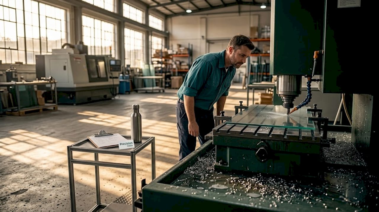
Mechanical glass machining covers a family of processes united by direct contact between a diamond abrasive tool and the glass substrate. CNC integration has transformed this from a craft skill into a repeatable, high-precision manufacturing operation.
The typical mechanical workflow follows this sequence:
- Blank preparation. The glass blank is cut to approximate size, then mounted and centred with reference to the optical or functional axis. Blank centring accuracy directly affects all downstream form tolerances.
- CNC edging. The perimeter is machined to profile using diamond wheels. CNC glass edging controls speed, pressure, and coolant flow automatically, removing operator variability and producing consistent edge safety across production batches.
- Curve generation. For lenses and curved optical elements, a curve generator defines the radius geometrically through the axis angle between the spindle and the tool. Axis-angle geometry locks the radius by machine configuration rather than numerical control, which prevents radius chasing and assures batch-to-batch repeatability. CNC curve generators achieve ±5 µm radius tolerances on 100 mm optical blanks using diamond cup wheels.
- Fine grinding and lapping. Subsequent grinding stages progressively reduce the damaged layer depth. Each stage uses a finer abrasive grade and lower contact force. Coolant flow rate and chemistry are tightly managed to prevent thermal shock.
- Polishing. Final polishing removes residual sub-surface damage and brings surface roughness to specification. Pitch polishing and polyurethane pad polishing are the most common methods at this stage.
| Parameter | Rough grinding | Fine grinding | Polishing |
|---|---|---|---|
| Abrasive grit (µm) | 40–100 | 10–25 | 1–5 |
| Material removal rate | High | Medium | Low |
| Sub-surface damage depth | 20–50 µm | 5–15 µm | <1 µm |
| Surface roughness (Ra) | 0.5–2 µm | 0.1–0.5 µm | <0.02 µm |
Pro Tip: Coolant flow rate is the most frequently underspecified parameter in CNC glass grinding. Inadequate coolant causes thermal micro-cracking that polishing cannot fully remove. Validate flow rate at each spindle speed change during process development.
For teams managing the broader precision glass manufacturing workflow, integrating CNC edging with CAD/CAM from the design stage prevents costly re-working when tolerances tighten at later stages.
Laser-based glass machining: ultrafast cutting and ablation
Laser machining and mechanical cutting operate on fundamentally different physical principles. Where mechanical processes apply force, laser processes deliver photon energy so rapidly that material is ablated before heat can conduct into the surrounding glass. This is the basis of the explanation for why ultrafast lasers have become a production tool in demanding sectors.
The key distinctions are:
- Picosecond versus femtosecond lasers. Both operate in the ultrafast regime, but femtosecond pulses (below 1 ps) are used for extreme requirements, particularly for ultra-thin glass below 100 microns where any heat-affected zone is unacceptable. Picosecond systems are the practical choice for thicker substrates where cost and throughput matter.
- Cold ablation. Ultrafast pulses remove material through direct ionisation rather than thermal melting. The result is low heat-affected zones and minimal micro-cracking, producing edge strength that mechanical scribing cannot match.
- Coated and multi-layer glass. Laser cutting handles coated architectural glass, laminated displays, and multi-layer optical assemblies without delaminating functional coatings. Mechanical cutting frequently damages these interfaces.
- Complex geometries. Laser paths are software-defined, so internal cutouts, curved profiles, and fine features that would require complex fixturing in mechanical machining are straightforward operations.
Modern nanoPerforation laser cutting reduces edge breakouts by a factor of 10 compared to traditional methods, resulting in substantially stronger finished edges.
Laser technology is not a universal replacement for mechanical processes. The capital cost of femtosecond systems is significantly higher, and throughput per unit cost still favours mechanical methods for thick, simple geometries. There is no universal laser for glass machining. The selection decision depends on substrate thickness, geometry complexity, and production budget, considered together.
For engineers working in aerospace and medical applications, laser machining is increasingly the default for thin substrates and complex profiles, while mechanical processes handle bulk material removal on thicker blanks.
Hybrid and finishing processes: MRF, laser polishing, and inspection
Achieving the surface quality required in semiconductor wafer handling, optical instruments, and implantable medical devices demands more than mechanical polishing. A class of advanced finishing processes bridges the gap between precision grinding and atomic-level smoothness.
Magnetorheological finishing (MRF) uses a magnetically stiffened fluid ribbon carrying fine abrasive particles. The ribbon conforms to complex aspheric surfaces and removes material at sub-nanometre precision. MRF achieves Ra < 7 nm on complex geometries where conventional polishing tools cannot maintain consistent contact pressure.
Laser polishing complements MRF on simpler geometries, using controlled laser energy to locally reflow the surface layer and eliminate micro-roughness without mechanical contact. It is particularly effective on fused silica components where contamination from abrasive particles is unacceptable.
Inspection at this level requires correspondingly capable metrology:
- White light interferometry for surface form and roughness mapping across the full aperture.
- 3D profilometry for micro-crack and pit detection at the nanometre scale.
- Subsurface scatter imaging to detect damage below the polished surface that would not appear in conventional surface inspection.
Quality standards in precision manufacturing specify which inspection methods apply at each production stage, not just at final acceptance. Catching sub-surface damage after polishing is expensive. Detecting it after grinding is not.
Pro Tip: Schedule white light interferometry inspection after each grinding stage, not only at final inspection. This identifies developing sub-surface damage before it propagates through polishing cycles, reducing scrap rates on high-value optical blanks.
For specialist applications, nitrogen atmosphere control in electrochemical discharge micromachining reduces tool wear energy by 33% and stabilises material removal. This remains an underused technique in production settings but is worth evaluating for micromachining of borosilicate components at high volumes.
Process selection: applications, tolerances, and design alignment
Choosing the correct glass machining process is not a linear decision. It requires concurrent assessment of four factors: glass composition, component geometry, production volume, and the tightest tolerance on the drawing.
| Factor | Mechanical process preferred | Laser process preferred |
|---|---|---|
| Substrate thickness | >3 mm | <3 mm or ultra-thin (<0.1 mm) |
| Geometry complexity | Simple profiles, flat edges | Internal cutouts, fine features, curves |
| Coatings present | No coatings or robust layers | Functional coatings, laminates |
| Tolerance class | ±25 µm and above | ±10 µm and below on edge form |
| Production volume | High volume with proven tooling | Low to medium, or high-mix |
In aerospace, precision glass components for head-up displays and sensor windows require both tight dimensional tolerances and high edge strength under vibration loading. The typical approach combines CNC curve generation for form accuracy with laser processing for edge finishing. In medical devices, borosilicate microfluidic chips demand micron-level channel definition achievable only with femtosecond laser ablation. In electronics, cover glass for display modules requires high-throughput laser cutting to maintain edge strength in thin substrates.
CNC automation standardises coolant flow and pressure variables, substantially reducing chipping in mass production. However, automation does not replace process engineering. Thin substrates and complex shapes still require individual fixture design and validated tool paths before production begins.
Pro Tip: On multi-process jobs, always machine form before finishing edges. Edge machining applies concentrated stress at the boundary. If edge processing precedes surface grinding, that stress propagates into the bulk and creates sub-surface damage that polishing will not remove.
My perspective on where glass machining is heading
I’ve worked closely with precision glass manufacturing across aerospace and semiconductor programmes, and the single most common mistake I see is treating glass machining as a series of independent operations rather than a connected system. Engineers optimise a grinding stage in isolation, then are surprised when the polishing step reveals damage that originated two processes earlier.
What I’ve learned is that the micro-fracture budget is the governing constraint. Every contact operation, every thermal gradient, every fixture clamping point consumes some of that budget. The manufacturers who achieve consistently high yields understand this and track sub-surface damage accumulation across the process chain, not just at final inspection.
The integration of laser and mechanical processes is where the most capable facilities are focusing attention now. Neither technique is sufficient alone for the most demanding components. Mechanical processes provide material removal efficiency; laser processes provide edge quality and geometric freedom. Hybrid approaches that use each where it performs best are producing results that neither method achieves independently.
The next significant shift will come from in-process metrology. Real-time interferometry and force sensing during grinding are moving from research labs into production. When they arrive at scale, the remaining variability in precision glass machining will drop considerably.
— Alexandra
Precision glass machining with Glassprecision
Glassprecision brings together the full spectrum of mechanical, laser, and advanced finishing techniques discussed in this article, applied across defence, aerospace, medical, and electronics sectors. Every component is designed, fabricated, and inspected against documented quality standards, with tolerances tailored to the application rather than defaulted to standard grades.

Whether your project requires CNC-ground optical blanks, femtosecond-cut thin substrates, or MRF-polished aspheric surfaces, our team works from your design parameters to deliver components that meet specification first time. Explore our precision glass capabilities and our dedicated optical components range to see how we can support your programme. Contact us directly to discuss bespoke machining solutions for your application.
FAQ
What does glass machining involve technically?
Glass machining encompasses mechanical processes such as CNC grinding, edging, and polishing, alongside laser cutting and ablation techniques. The goal in every case is to shape glass to precise dimensional and surface quality specifications without introducing damaging micro-fractures.
How does laser glass cutting differ from mechanical cutting?
Laser cutting uses ultrafast photon pulses to ablate material without sustained heat transfer, producing minimal micro-cracking and stronger edges. Mechanical cutting applies direct abrasive contact, which suits thicker substrates and high-volume production but requires subsequent finishing to remove sub-surface damage.
When should femtosecond lasers be used over picosecond systems?
Femtosecond lasers are specified for ultra-thin glass below 100 microns or where heat-affected zones must be negligible. Picosecond systems are the practical choice for standard-thickness substrates where cost and throughput are also considerations.
What is magnetorheological finishing and why does it matter?
MRF uses a magnetically controlled abrasive fluid to finish complex optical surfaces to Ra < 7 nm, a level that conventional polishing cannot reliably reach on aspheric geometries. It is production-critical for semiconductor and high-performance optical components.
How do engineers select the right glass machining process?
Process selection depends on glass type, substrate thickness, geometry complexity, surface finish requirements, and production volume. Mechanical processes suit thick, high-volume parts; laser processes suit thin, complex, or coated substrates. The tightest tolerance on the drawing should always be the primary decision driver.


