

A plate beamsplitter is a flat optical substrate, typically glass, that splits an incident beam into two paths: one transmitted through the substrate and one reflected from its coated surface. Most designs operate at a 45° angle of incidence (AOI), producing a reflected beam at 90° to the transmitted beam. Plate beamsplitters are fabricated using dielectric materials and employed at this 45° AOI as standard, making them a core component in interferometers, laser delivery systems, fluorescence microscopes, and fibre-optic telecoms.
For UK engineers specifying an optical beamsplitter today, the choice of type maps fairly directly to application:
- Non-polarising dielectric plate: broadband imaging, general-purpose optical systems, Mach–Zehnder interferometers where polarisation state must be preserved.
- Polarising plate (Brewster angle): polarisation analysis, ellipsometry, and laser systems where you need to separate s- and p-polarisation cleanly.
- Dichroic plate: fluorescence instruments and multi-wavelength systems requiring spectral band routing.
- Wedged or pellicle plate: imaging paths where ghost reflections must be eliminated; pellicles suit ultrafast lasers with low group-delay dispersion (GDD) requirements.
Quality assurance matters as much as optical specification. Procurement teams should request ISO 9001-compliant documentation, including spectral R/T curves, flatness reports, and laser damage threshold (LDT) data, before committing to a supplier.
Pro Tip: For interferometry applications such as Mach–Zehnder or Michelson configurations, flatness and wavefront distortion are the specifications to prioritise above splitting ratio tolerance. A 50:50 split is useless if wavefront error degrades fringe visibility.
Table of Contents
- How does a plate beamsplitter work?
- What types of plate beamsplitter are available?
- What specifications should you read on a plate beamsplitter datasheet?
- How do you choose the right plate beamsplitter for your application?
- Plate versus cube beamsplitters: which should you specify?
- How do you mount, align and handle a plate beamsplitter?
- Ordering custom plate beamsplitters in the UK with Precision Glasses
- Quick specification checklist for RFQs and procurement documents
- Key takeaways
- Why the specification gap matters more than the coating choice
- Precision Glasses: custom plate beamsplitters for demanding applications
- Useful sources and further reading
How does a plate beamsplitter work?
At its most fundamental level, a plate beamsplitter exploits partial reflectance at a coated optical surface. When a beam strikes the coating at 45° AOI, a fraction of the incident intensity is reflected and the remainder is transmitted. The exact split depends on the coating design, the substrate refractive index, and the polarisation state of the incoming beam.

Ray geometry and substrate effects
BK7 borosilicate glass (refractive index n ≈ 1.52 at 589 nm) and fused silica (n ≈ 1.46) are the two most common substrate materials. At 45° AOI, the refracted ray inside the substrate travels at an angle determined by Snell’s law, which affects the optical path length through the glass and, consequently, the lateral displacement of the transmitted beam. Fused silica is preferred for deep-UV applications and high-power lasers because of its lower absorption and higher thermal stability; BK7 suits visible and near-IR work at moderate power levels. The optical properties of the substrate directly influence wavefront quality and thermal performance.
Coating types and their trade-offs
Dielectric thin-film coatings produce wavelength-dependent R/T behaviour that varies with polarisation, while metallic half-silvered coatings provide broader, more polarisation-insensitive splitting but with higher absorption. In practice, this means:
- Dielectric coatings offer high efficiency (low absorption loss), but the R/T ratio shifts with wavelength and polarisation. They are the right choice for laser lines and narrow spectral bands.
- Metallic coatings (e.g., aluminium or silver half-mirror) split more uniformly across a broad spectrum but absorb a measurable fraction of incident power, which becomes a thermal management issue at higher irradiance.
- Dichroic coatings are engineered so the R/T ratio varies strongly with wavelength, routing spectral bands to separate output ports.
Phase shifts and interferometry
Beam splitters introduce phase shifts that depend on polarisation and angle, and these shifts must be accounted for in interferometric systems where phase relationships determine output. A dielectric coating can introduce a phase difference between reflected and transmitted beams that is not simply 0° or 180°. In a Mach–Zehnder or Michelson interferometer, an uncharacterised phase shift will offset fringe position and introduce measurement error.
Phase shifts introduced by reflections at dielectric surfaces can alter interferometer outputs in ways that are not obvious from the splitting ratio alone. Engineers should verify phase behaviour experimentally or request phase data from the supplier where it is available, particularly for precision metrology applications.
Substrate flatness interacts directly with wavefront quality. A plate with poor flatness introduces optical path difference (OPD) across the beam aperture, degrading spatial coherence. For interferometry, flatness better than λ/10 (at 633 nm) is a common requirement; for general imaging, λ/4 is often acceptable.
What types of plate beamsplitter are available?
Plate beamsplitters are used across fibre-optic telecoms, laser systems, and optical instrumentation including heads-up displays and cameras. Each variant addresses a specific set of application constraints.
- Non-polarising dielectric plate: Maintains the polarisation state of the input beam while splitting intensity. Suited to broadband imaging, general optical benches, and interferometers. The trade-off is that R/T performance is wavelength-dependent, so you need to specify the operating band precisely.
- Polarising plate (Brewster angle design): At Brewster’s angle, p-polarisation is fully transmitted and s-polarisation is strongly reflected, giving near-perfect polarisation separation. These designs are constrained to a fixed AOI and a narrow wavelength range, which limits their flexibility.
- Dichroic plate: Dichroic coatings can be engineered so the R/T ratio varies strongly with wavelength, enabling spectral splitting for fluorescence microscopy, multi-band imaging, and wavelength-division multiplexing. The coating design is application-specific and typically requires a custom specification.
- Wedged plate: The rear surface is polished at a small wedge angle (typically 0.5°–3°) relative to the front surface. This walks the ghost reflection from the rear surface out of the optical path, preventing interference fringes and double-image artefacts.
- Pellicle beamsplitter: An ultra-thin membrane (typically 2 µm nitrocellulose or polyester) stretched over a frame. Near-zero substrate thickness means negligible GDD, making pellicles the preferred choice for ultrafast pulse applications. They are fragile and sensitive to acoustic vibration.
- Beam sampler: A low-reflectance plate (R typically 1%–10%) used to divert a small fraction of a beam for power monitoring or diagnostics without significantly attenuating the main beam.
| Type | Best use case | Key limitation |
|---|---|---|
| Non-polarising dielectric | Broadband imaging, interferometry | R/T varies with wavelength and polarisation |
| Polarising (Brewster) | Polarisation analysis, laser systems | Fixed AOI, narrow wavelength range |
| Dichroic | Fluorescence, multi-band instruments | Custom coating required per application |
| Wedged plate | Imaging paths, coherent systems | Slight beam deviation from wedge |
| Pellicle | Ultrafast lasers, low-GDD systems | Fragile, vibration-sensitive |
| Beam sampler | Power monitoring, diagnostics | Low reflectance only |
Pro Tip: When specifying a wedged plate for a coherent imaging system, confirm the wedge angle is sufficient to displace the ghost beam beyond the detector aperture at your working distance. A 1° wedge at typical working distances displaces the ghost reflection sufficiently to move it outside the detector aperture, preventing interference effects.
What specifications should you read on a plate beamsplitter datasheet?
A datasheet that does not include spectral R/T curves, polarisation sensitivity data, and a flatness specification is incomplete. Engineers should request spectral R/T curves, polarisation sensitivity curves, surface flatness and wavefront reports, and laser damage threshold test data as part of acceptance testing. Here is what each parameter means in practice.
| Specification | What to look for | Practical note |
|---|---|---|
| Splitting ratio (R/T) | Stated at your operating wavelength and AOI | Confirm tolerance (e.g., 50:50 ±5%) |
| Wavelength range | Must cover your full operating band | Dielectric coatings narrow this range |
| Polarisation sensitivity | ΔR between s- and p-pol | <5% for non-polarising; >90% for polarising |
| Substrate material | BK7 or fused silica | Fused silica for UV or high-power |
| Thickness | Stated in mm | Affects OPD and lateral beam displacement |
| Wedge angle | Degrees or arcminutes | Required for ghost suppression |
| AR coating (rear surface) | Residual reflectance at λ | R < 0.5% per surface is typical |
| Surface quality | Scratch/dig per MIL-PRF-13830 | 20/10 for laser; — for general use |
| Flatness | λ/N at 633 nm | λ/10 for interferometry; λ/4 for imaging |
| Wavefront distortion | Waves RMS or P-V | Measure after mounting, not just in free air |
| Laser damage threshold | J/cm² (pulsed) or W/cm² (CW) | Must exceed your peak fluence with margin |
| Environmental rating | Temperature range, humidity | Relevant for field-deployed instruments |
Reading spectral curves correctly is as important as the numbers themselves. A dielectric coating will show a sharp R/T transition at the band edges; a metallic coating will show a flatter, broader curve with a lower peak efficiency. Polarisation curves for a nominally non-polarising plate should show R_s and R_p tracking closely across the operating band. A large divergence between R_s and R_p at your wavelength is a red flag for polarisation-sensitive applications.
For substrate selection, the choice between BK7 and fused silica affects not only transmission range but also thermal expansion (BK7 CTE ≈ 7.1 × 10⁻⁶/K versus fused silica ≈ 0.55 × 10⁻⁶/K), which matters in thermally cycled environments.

Pro Tip: For interferometry, prioritise flatness and wavefront distortion. For high-power laser delivery, LDT and substrate absorption are the critical parameters. For broadband imaging, check polarisation sensitivity across the full wavelength band, not just at the centre wavelength.
Specification checklist for RFQs:
- Splitting ratio (R/T) with stated tolerance at operating wavelength
- Full spectral R/T curves (s- and p-polarisation separately)
- Polarisation sensitivity (ΔR or ΔT across operating band)
- Substrate material, grade, and refractive index at operating wavelength
- Substrate thickness and wedge angle (if applicable)
- Coating type (dielectric, metallic, dichroic) and AR coating residual reflectance
- Surface quality (scratch/dig per MIL-PRF-13830 or equivalent)
- Flatness (λ/N at 633 nm, measured over clear aperture)
- Wavefront distortion (waves RMS, P-V)
- Laser damage threshold (test method, pulse duration, wavelength)
- Environmental ratings (temperature range, humidity, cleaning compatibility)
- Batch traceability and material certificates
- Inspection report and test data package
How do you choose the right plate beamsplitter for your application?
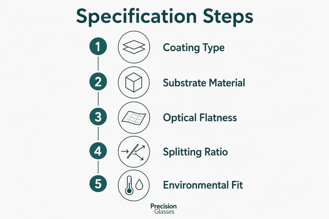
Start with your system requirements, not the catalogue. The correct sequence is: define the optical constraints first, then identify the coating and substrate, then confirm the mechanical and environmental fit.
Step 1: Define optical requirements
- Operating wavelength(s) and bandwidth
- Required splitting ratio and tolerance
- Polarisation state of the input beam and whether polarisation must be preserved
- Beam diameter and required clear aperture
- Wavefront quality budget for the full system
Step 2: Assess power and energy constraints
- Peak and average irradiance at the beamsplitter surface
- Pulse duration (for pulsed lasers)
- Whether the coating must survive long-term CW exposure or single-shot high-energy pulses
Step 3: Select substrate and coating
- BK7 for visible/NIR at moderate power; fused silica for UV, deep-UV, or high-power applications
- Dielectric coating for efficiency and low absorption; metallic for broadband, polarisation-insensitive splitting; dichroic for spectral routing
- Optical cement in cube beamsplitters can degrade under UV or high laser exposure; plate designs avoid cemented interfaces, which is an advantage in demanding laser environments
Step 4: Confirm mechanical and environmental fit
- Mounting method: kinematic mounts, fixed mounts, or bonded assemblies
- Operating temperature range and thermal cycling requirements
- Humidity and chemical exposure (relevant for field instruments)
- Cleaning compatibility with the coating type
Pro Tip: Red flags in vendor datasheets: no LDT value stated, polarisation dependence listed as “low” without a number, spectral curves absent or shown only at normal incidence rather than 45° AOI. Any of these gaps should trigger a request for supplementary data before ordering.
Procurement questions to include in an RFQ:
- Can you provide material batch certificates and refractive index measurement data?
- Are spectral R/T curves (s- and p-pol) measured at 45° AOI included in the test data package?
- What is the LDT test method and at what wavelength and pulse duration was it measured?
- What are the dimensional tolerances on thickness, diameter, and wedge angle?
- What is the standard lead time for this specification, and what is available for prototype quantities?
- Are ISO 9001 process records and inspection reports supplied with each batch?
Plate versus cube beamsplitters: which should you specify?
The choice between a plate and a cube is not simply a matter of preference. Each form factor has genuine technical advantages in specific contexts, and specifying the wrong one creates problems that cannot be corrected by alignment alone.
Plate beamsplitters typically exhibit lower chromatic aberration and can be produced in larger sizes at lower cost than cubic beamsplitters. For laboratory and imaging applications requiring large clear apertures, plates offer a better balance of cost, size, and chromatic performance.
| Dimension | Plate beamsplitter | Cube beamsplitter |
|---|---|---|
| Chromatic aberration | Lower (single substrate) | Higher (cemented prism pair) |
| Ghost reflections | Present (wedge or AR coating required) | Lower (internal geometry suppresses ghosts) |
| Polarisation sensitivity | Varies with coating; non-pol types available | Generally lower polarisation sensitivity |
| Wavelength range | Broad; coating-limited | Cement limits UV and high-power use |
| Thermal performance | Better at high power (no cement) | Cement can degrade under UV/high power |
| Available aperture | Larger sizes achievable at lower cost | Larger sizes are costly and heavy |
| Mechanical mounting | Requires careful kinematic mounting | Self-contained; easier to mount |
| Lateral beam displacement | Present (substrate thickness) | Minimal |
When to choose a cube:
- Compact, fixed-alignment systems where mechanical simplicity matters
- Applications where ghost suppression is critical and a wedged plate is not practical
- Systems operating at moderate power levels in the visible range
When a plate is the better choice:
- High-power or UV laser systems where cement degradation is a concern
- Large-aperture systems (>50 mm) where cube cost and weight become prohibitive
- Broadband imaging systems where chromatic aberration from the cement layer is unacceptable
- Custom dichroic or polarising configurations that are difficult to implement in a cemented cube geometry
How do you mount, align and handle a plate beamsplitter?
Correct mounting and handling practice determines whether a plate beamsplitter performs to its datasheet specification in service. Errors at this stage introduce wavefront distortion, ghost images, and coating damage that no amount of optical design can compensate for.
Mounting
- Use a kinematic or semi-kinematic mount that contacts the plate at its edge, not its optical surface. Clamping stress across the aperture introduces birefringence and wavefront error.
- Orient a wedged plate so the ghost reflection is deflected away from the detector or image plane, not towards it. Check the deflection direction before final assembly.
- Allow for thermal expansion: do not over-constrain a large plate in a rigid mount. A compliant retaining ring or RTV bond at the edge accommodates differential thermal expansion.
- For CNC-machined mounts and housings, precision machined components with tight angular tolerances on the mount seat reduce the alignment burden on the optical adjustment.
Alignment
- Set the AOI to 45° using an autocollimator or a reference beam. A 1° error in AOI shifts the R/T ratio measurably for dielectric coatings.
- Verify the splitting ratio in situ with a calibrated power meter on both output ports. Compare against the datasheet value at your operating wavelength.
- Measure wavefront distortion after mounting using a Fizeau interferometer or shear plate. Mounting stress often degrades flatness by λ/4 or more relative to the free-air measurement.
- Check for ghost beams by scanning a detector across the output aperture. A wedged plate should show the ghost displaced outside the clear aperture.
Handling and cleaning
- Handle plates with clean nitrile or latex gloves. Fingerprints on a dielectric coating introduce scatter and can etch the coating if left in place.
- Clean with reagent-grade isopropanol or acetone on a lint-free optical tissue, using a single-pass drag technique. Never scrub a dielectric surface.
- Store in a dry, dust-free environment. Humidity above 80% RH can degrade some metallic coatings over time.
- Pellicle beamsplitters must never be cleaned; replace them if contaminated.
Pro Tip: During commissioning, measure the power ratio (P_reflected / P_transmitted) and the beam profile on both output ports. A distorted beam profile on the transmitted port often indicates mounting stress rather than a coating defect, and can be corrected by relaxing the mount.
Ordering custom plate beamsplitters in the UK with Precision Glasses
Precision Glasses manufactures custom precision-engineered glass components for defence, aerospace, medical devices, and scientific instrumentation, supplying UK procurement teams with the documentation and traceability that regulated procurement requires.
Capabilities relevant to plate beamsplitter orders include:
- Substrate materials: BK7, fused silica, and specialised optical glasses selected for the application’s wavelength range and thermal environment. See the glass for photonics reference for material property detail.
- Coatings: dielectric single-layer and multi-layer thin-film coatings, dichroic coatings, and broadband AR coatings on rear surfaces, all specified to customer wavelength and AOI requirements.
- Tolerances: tight dimensional tolerances on thickness, diameter, and wedge angle; surface quality to 20/10 scratch/dig for laser applications.
- Batch traceability: material certificates, refractive index data, and process records supplied per batch.
- Test data: spectral R/T curves (s- and p-polarisation at 45° AOI), flatness/interferogram reports, and LDT data available on request.
The ordering process follows a structured sequence:
- Specification review: submit your drawing or RFQ with the checklist parameters above. Precision Glasses’ engineering team reviews feasibility and flags any specification conflicts.
- Drawing and tolerance confirmation: dimensional drawings are agreed and tolerances confirmed against manufacturing capability.
- Prototype fabrication: prototype quantities are produced and tested against the agreed specification before volume production.
- Production QA: each production batch is inspected against the specification. Inspection reports and spectral data are issued with the delivery.
- Delivery and documentation: components are delivered with a full documentation package including material certificates, inspection reports, and test data.
UK procurement teams working to ISO 9001 quality standards will find Precision Glasses’ process controls and documentation aligned with standard procurement requirements. Lead times for custom specifications vary with coating complexity and substrate availability; standard BK7 plates with dielectric coatings are typically achievable within a few weeks for prototype quantities.
Pro Tip: Submit a complete specification at the RFQ stage, including LDT requirements and environmental ratings. Incomplete RFQs extend lead times because they require clarification rounds. The checklist in the section above is designed to cover everything a fabricator needs to quote accurately.
Quick specification checklist for RFQs and procurement documents
Use this checklist verbatim in your RFQ or purchase order to avoid specification gaps.
Optical parameters:
- R/T splitting ratio with tolerance (e.g., 50:50 ±5% at 532 nm, 45° AOI, s-polarisation)
- Wavelength band (e.g., 500–550 nm) and whether s-pol, p-pol, or average is specified
- Polarisation sensitivity: maximum ΔR between s- and p-pol across the operating band
- Coating type: dielectric / metallic / dichroic; AR coating residual reflectance per surface
Substrate and dimensional parameters:
- Substrate material (BK7 / fused silica / other) and grade
- Diameter or clear aperture (mm), with tolerance
- Thickness (mm), with tolerance
- Wedge angle (degrees or arcminutes), if required
Surface and wavefront parameters:
- Surface quality: scratch/dig per MIL-PRF-13830 (e.g., 20/10 for laser use)
- Flatness: λ/N at 633 nm over clear aperture (e.g., λ/10)
- Wavefront distortion: waves RMS or P-V at operating wavelength
Laser and environmental parameters:
- Laser damage threshold: J/cm² (pulsed) or W/cm² (CW), at stated wavelength and pulse duration
- Operating temperature range (°C) and humidity range (%RH)
- Cleaning compatibility (specify if solvent cleaning is required)
Acceptance test data to request:
- Spectral R/T curves (s- and p-polarisation, measured at 45° AOI)
- Polarisation sensitivity curves across operating band
- Interferogram or flatness report over clear aperture
- LDT test report (method, wavelength, pulse duration, result)
- Material batch certificate and refractive index measurement
Procurement note: For standard sizes (25 mm and 50 mm diameter, BK7, dielectric 50:50 coating), UK suppliers typically quote shorter lead times than for custom substrates or specialised coatings. Custom dichroic or fused silica plates with tight LDT requirements will carry longer lead times. Pricing varies considerably with coating complexity, substrate grade, and batch size; always request a formal quotation against a complete specification rather than relying on catalogue prices for custom work.
Pro Tip: Request that spectral curves be measured at 45° AOI, not at normal incidence. Many catalogue datasheets show normal-incidence data, which does not represent the actual performance of a plate beamsplitter in service.
Key takeaways
A plate beamsplitter’s performance is determined by coating type, substrate material, and flatness: specify all three precisely, request measured data at 45° AOI, and verify wavefront distortion after mounting.
| Point | Details |
|---|---|
| Prioritise flatness for interferometry | Specify λ/10 flatness at 633 nm and request an interferogram report for Mach–Zehnder or Michelson systems. |
| Check LDT for laser applications | Request LDT data at your operating wavelength and pulse duration; fused silica substrates outperform BK7 at high power. |
| Request 45° AOI spectral curves | Catalogue data at normal incidence does not represent in-service performance; always specify measurement at 45° AOI. |
| Use wedged plates to suppress ghosts | A wedged rear surface displaces ghost reflections out of the optical path, preventing fringe artefacts in coherent systems. |
| Precision Glasses for custom UK orders | Precision Glasses supplies custom plate beamsplitters with batch traceability, spectral test data, and ISO 9001-aligned documentation for UK procurement. |
Why the specification gap matters more than the coating choice
Most engineers spend their specification effort on the coating: splitting ratio, wavelength, polarisation. That is the right instinct, but in practice the failures we see most often come from what is not specified rather than from the coating itself.
Wavefront distortion after mounting is the most common source of underperformance. A plate that measures λ/10 flatness in free air can easily degrade to λ/4 or worse when clamped in a poorly designed mount. The coating is fine; the mount is the problem. Yet the mount is rarely specified in the RFQ, and the wavefront is rarely measured after installation.
The second gap is phase data. For interferometric applications, the phase shift introduced by the beamsplitter coating is as important as the splitting ratio. Most commercial datasheets do not include it. Requesting phase data at the RFQ stage is unusual enough that some suppliers will not have it readily available, but it is the right question to ask for any precision metrology application.
The third gap is environmental qualification. A plate beamsplitter that performs well on the optical bench may degrade in a field instrument exposed to humidity cycling or vibration. Metallic coatings are more susceptible to humidity than dielectric ones; pellicles are vulnerable to acoustic pressure. These constraints are rarely stated in catalogue datasheets and must be raised explicitly in procurement.
The practical lesson: a complete specification is worth more than a premium coating. Precision Glasses’ design review process is structured to surface these gaps before fabrication begins, which is why we recommend engaging the engineering team at the specification stage rather than at the purchase order stage.
Precision Glasses: custom plate beamsplitters for demanding applications

Precision Glasses delivers custom optical components to defence, aerospace, medical device, and scientific instrumentation manufacturers across the UK, with the documentation and traceability that regulated procurement demands. For plate beamsplitter orders, that means spectral R/T curves measured at 45° AOI, flatness reports, LDT data, and material batch certificates supplied as standard with every production batch.
Our fabrication process covers BK7 and fused silica substrates, dielectric and dichroic coatings, wedged and flat geometries, and surface quality to 20/10 scratch/dig for laser applications. Every order goes through a structured specification review before fabrication begins, so tolerance conflicts and missing parameters are resolved before they affect lead times.
To request a technical review or submit an RFQ, visit glassprecision.com or contact our engineering team directly. Prototype quantities are available, and our team can advise on specification trade-offs before you commit to a production run.
Useful sources and further reading
The references below are the primary sources for the technical claims in this article and are suitable for use in procurement documents and acceptance test plans.
- Beam splitter — Wikipedia: Conceptual grounding on beamsplitter types, phase shifts, and system applications. Useful for understanding Fresnel coefficients, polarisation effects, and interferometer configurations.
- Understanding beamsplitters: Types, principles, and applications — AZoM: Practical treatment of plate beamsplitter fabrication, AOI conventions, chromatic aberration comparison with cubes, and acceptance test recommendations. Directly applicable to procurement specifications.
For substrate selection and optical material properties:
- Glass material selection for precision industries: Covers BK7, fused silica, and specialised optical glasses with mechanical and optical property data relevant to beamsplitter substrate selection.
- Optical coatings explained: Technical explanation of dielectric and dichroic coating technology, test methods, and inspection criteria.
Standards relevant to UK procurement:
- MIL-PRF-13830: The US military standard for surface quality (scratch/dig) widely referenced in optical component procurement worldwide, including UK defence and scientific procurement.
- ISO 10110: International standard for the preparation of drawings for optical elements and systems, including surface quality, form tolerance, and coating specifications. Recommended for all custom optical component RFQs.
- ISO 9001: Quality management system standard. Suppliers operating under ISO 9001 provide documented process controls, inspection records, and traceability, which are standard requirements in UK regulated procurement.
Pro Tip: When citing acceptance criteria in a purchase order, reference the specific clause of ISO 10110 or MIL-PRF-13830 that applies to each parameter. This removes ambiguity about measurement method and pass/fail criteria, and gives both parties a shared reference for dispute resolution.


